Vermes
Advanced Member level 4
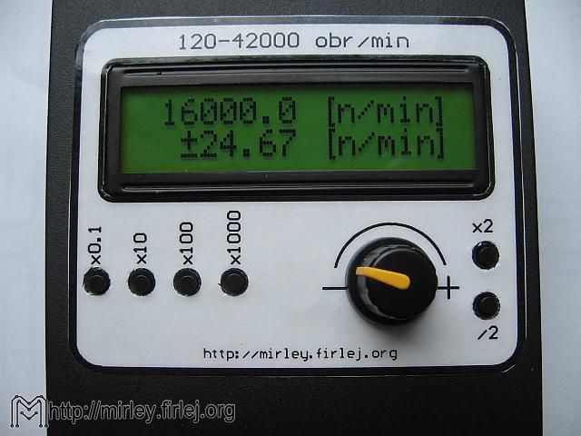
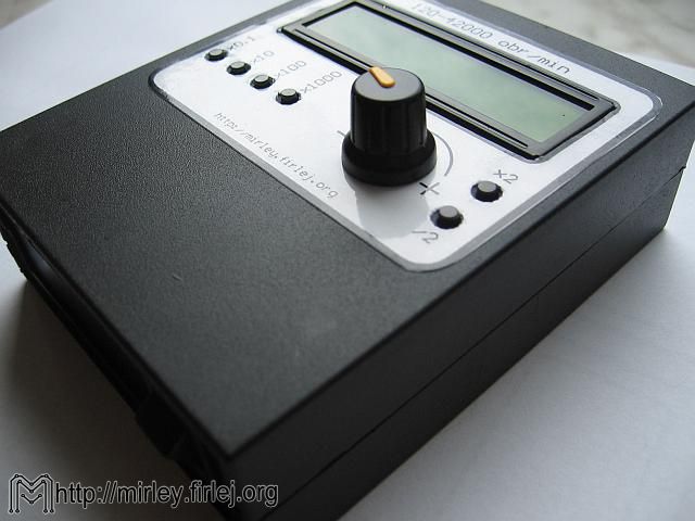
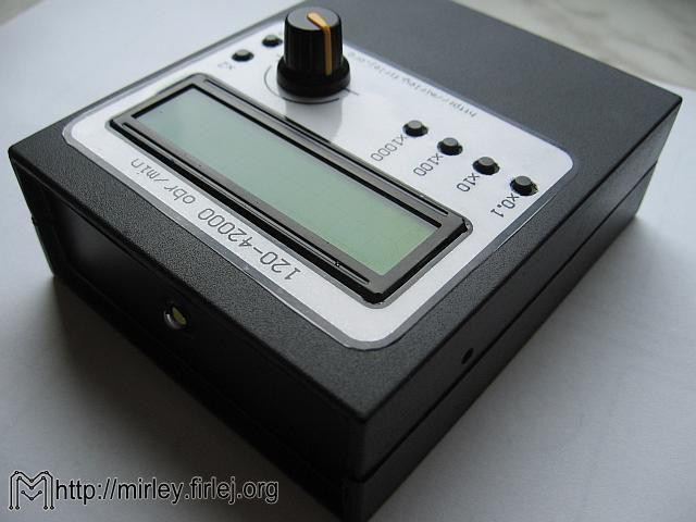
Presented system is a meter of rotational speed of electric motors. Its main advantage is non-invasive measurement, what means that it lights a rotating object with a high power LED. The measurement is done by setting the frequency of rotations (setting a still image after lighting with the strobe light from a LED) using pulser. The measurement can be made without stopping the device under test.
The system was built based on a microcontroller Atmega8, and set rotations are presented on the LCD. Additionally, the system also shows an error as a result of rounding the calculated value for the timer divider, while the frequency measurements of the flashes generated allowed to make a meter, not just the rate of rotation from the system.
Control is via rotary encoder and 6-buttons keyboard. The whole device can be powered by batteries, since due to the pulse nature of the LED work, the whole does not consume a lot of power. The system successfully fits the popular housing KM35, where is also place for 9V battery.
Schema:
The heart of the system and its most important part is microcontroller U1 (Atmega8-16AU), which works on timing from quartz crystal X1 (16MHz). Additional capacitors C1 (22pF) and C2 (22pF) are necessary for the proper operation of the resonator. Prog connector is used as the programming interface. It contains a set of signals needed during serial programming. This connector is necessary because the microcontroller is in SMD housing, what makes it impossible to program in an external circuit. Capacitor C5 (100nF) filters the microcontroller power supply. Capacitors C6 (100nF) and C7 (100nF) soften slope generated by the IMP pulser, which facilitates the smooth support in the program. Buttons S1-S6 (uSwitch) are an additional keyboard of the device. LED power 0,5W is the element that generates flashes. Its current is limited by resistor R4 (30R/2W), and the LED is controlled by transistor T2 (BC337) and the resistor R3 (330R). The LED is connected directly to power, bypassing the stabilizer to minimize the impact of current pulses to the microcontroller and relieve the voltage regulator U2 (78L05). Capacitors C3 (220uF) and C4 (47uF) are necessary for the proper operation of the stabilizer. Presentation of results of the measurement is carried out on the display W1 (LCD 16x2). Its contrast is set using P1 (10k) and the backlight is possible to integrate programmatically via a T1 (BC556), R1 (47R) and R2 (3,3k).
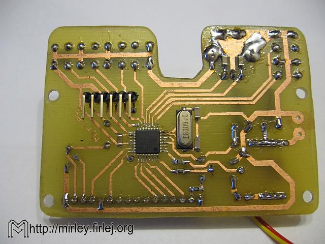
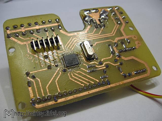
Mounting:
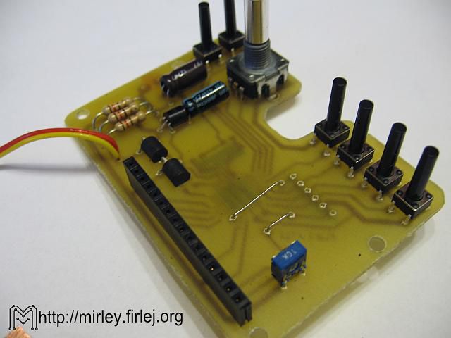
Work should begin with soldering two jumpers. Next in line should be capacitors and SMD resistors. They are to be elements in popular housings 0805 (2x1,2mm). Next in order should be the microcontroller U1, where it is important to pay attention to the pin numbers (assembly drawing in a mirror image is useful here). The buttons should have a length of 15mm shaft and they should be soldered to protrude slightly above the LCD display inserted in the drawer connector. It is important while mounting board in the housing. Similarly, the matter is with pulse transmitter. Potentiometer P1 has to be in standing housing, so the contrast can be adjusted from the side, when LCD inserted.
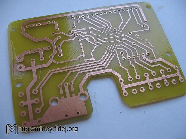
The board was designed, that it easily fits into the popular housing KM35. Everything is on the board that there is no need to connect buttons by cables. While cutting holes in the housing, picture with the distribution of holes may be useful. It should be pasted inside the housing with tape and then drill through the drawing. This facilitates the implementation of the housing.
The system was intended to supply 9V batteries, but also the power supply with voltage of 7-12V may be used.
Photos:

Calibration and measurements:
After programming the system using the initial version and calculation the timer divider, measurements showed deviations of the generated frequencies in relation to the theoretically expected value. This is due to the work with timer divider equal 1, the time needed for interrupt service and the time of reload the value in timer register. In the table below there are included measurements of the frequency generated on the output (f_p) in relation to the frequency that should be theoretically (f_i) and the corresponding values of rotations (rotations are multiplied by 10 to get the setting accuracy 0,1rev/min).
Data from the table were divided into two parts: from 60 to 480 rev/min and a second part from 480 to 42000 rev/min. This division results from the action of the program, in which there are two measuring ranges. The graphs below show the measurement points (dependence of theoretical rotations and measured rotations, converted from the measurement frequency) with matching calibration curves:
Quadratic dependence was adopted as a calibration curve, and its coefficients:
range 60-480 rotations:
- a= 1.88622104239405e-006
- b= 0.999905059864626
- c= 0.189869882714651
- a= 2.54573967680295e-007
- b= 0.996905226980814
- c= 1.00037985789872
Link to original thread (attachments) – Stroboskopowy Miernik Prędkości Obrotowej