Obanion
Newbie level 1
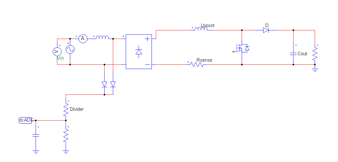
I'm working on sensing the mains input for a power factor-corrected boost converter so I can detect the zero-crossings and also detect the peak voltage. I have placed a voltage divider circuit before the voltage bridge so that the voltage can be stepped down to a range that falls within my ADC input range. An example of what I'm using can be found in the image. The capacitor on the output is 1uF and used for anti-aliasing purposes.
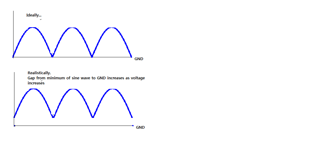
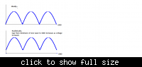
I'm having a problem where the rectified voltage isn't behaving as I would expect. Ideally, I want the zero-crossing of the rectified mains to correspond to the GND potential after the bridge. Instead, I'm seeing the voltage get close to 0 V, but never actually on it. In fact, as the voltage increases (e.g. from 120VAC to 240VAC), the gap from the minimum point on the rectified voltage to the GND of my circuit actually increases.
Now this wouldn't be a problem if the gap was consistent since I could add an offset or compensate it during software, but it's a big problem since it's varying with respect to peak input voltage. Is there any explanation for why the gap is increasing? I also measured at the input to the circuit right where it's plugged into the mains and that gap is still present, so I don't think it would be an EMI filter problem (there's one right after the diode bridge).
If I add a resistive divider (without diodes) for the live and neutral AC mains, the voltage is clamped to GND without any issue. I don't want to do this since it means I'll have to use two ADCs and add the signals together in software. I don't want to isolate this section either since there's isolation farther down the conversion chain (AD/DC to DC/DC).
Any comments or suggestions? Thanks