Continue to Site

Welcome to EDAboard.com

Welcome to our site! EDAboard.com is an international Electronics Discussion Forum focused on EDA software, circuits, schematics, books, theory, papers, asic, pld, 8051, DSP, Network, RF, Analog Design, PCB, Service Manuals... and a whole lot more! To participate you need to register. Registration is free. Click here to register now.

Switch direction on motor with roller switch and timers

Status
Not open for further replies.

Torbenc

Newbie level 5
Joined
Sep 26, 2011
Messages
9
Helped
0
Reputation
0
Reaction score
0
Trophy points
1,281
Activity points
1,357
Hi

Im building an automatic chicken door opener for my but are having some problems.

I had all parts laying around, and where I live a commercial door opener cost $300.


I have tried to assembly it as I thought it would work, but with no luck..

I have these parts:

2 x 12v timers (**broken link removed**
2 x Roller microswitches Switches - Microswitches - MCROLLER
1 x motor (from a electric drill - cheap and low gearet)

The plan was that timer 1 should open the relay at 8 a clock, microswitch 1 will let the motor turn clockwise, so it will open the door, when hitting microswitch 2, it will stop turning, and the current are set so the motor will turn counter clockwise.
At 21 a clock, timer 2 (or 1?) will again open the relay, and the door will close, hit microswitch 1, and set the current to clockwise.

Hope you understand my plan.
 

The concept is good.

I assume the microswitch is momentary and you can choose between normally open and normally closed.

I assume the motor is DC rather than AC.

I believe you'll need two batteries.

You probably hoped you could get by with one battery. Don't know how to do that.

See if this circuit helps.

**broken link removed**

Note: both switches are closed while door is partway open. Therefore it is crucial that no more than one of the timers be ON while door is partway open.
 
Last edited:

Thank you, I will try that out.

Just remembered, that the only reason that I woul use the microswitches, was to control how long time the motor would run.

The timers puts out 1 min signal, and it will only take about 20 sec to open the door. Therefor it have to be switched of.
 

Yes, it is typical to shut off power that way, by putting a switch at the extreme of travel.

You could do the job with a single battery, and a single timer, if you were to construct an H-bridge. It would let you reverse motor direction.

You could do this with a double pole double throw switch.

It cannot be a momentary type but must remain in one of two positions, until the door toggles it. One position as the door reaches full open. The other position as the door shuts. You would need to attach some kind of 'hand' to the door (possibly short, possibly as tall as the door, depending on how your door works).

However you would still need switches (and/or additional control circuitry) to ensure power is cut off when the door reaches its extremes of travel.

It could get complicated and error-prone since it depends on secure attachment of switches.

Or a light beam might be an easy way to control door motion too.

---------- Post added at 14:54 ---------- Previous post was at 14:41 ----------

By the way...

I said a single timer could do the job, since the Ebay listing states that the timer can be set to perform more than one on/off event. That's if you use an H-bridge.
 

I've only seen micro switches of the momentary type. This means they would release while your door is in motion. The motor would shut off.

The only way to use momentary switches in an H-bridge, is if you rig a device to push on a pair of switches at a time, all the while the door is in motion.

The device might be rails that ride against the switch rollers.

It will require inventiveness.

Your components must be able to provide the maximum current your motor draws. It needs more current when starting up, or when stalled.

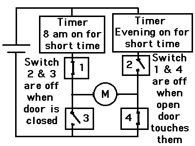
This circuit uses 1 battery and 2 timers. Again, only one timer at a time should ever be in ON mode.

94_1317266629.gif


EDIT: Don't build the above schematic. It will short circuit the way I described it. I left out the stipulation that the device pressing the switches must be made so it never allows all switches to conduct simultaneously. To do this might take cams, it might take rods, it might take notched wheels. Back to the drawing board...
 
Last edited:

Status
Not open for further replies.

Part and Inventory Search

Welcome to EDABoard.com

Sponsor

Back
Top