Continue to Site

Welcome to EDAboard.com

Welcome to our site! EDAboard.com is an international Electronics Discussion Forum focused on EDA software, circuits, schematics, books, theory, papers, asic, pld, 8051, DSP, Network, RF, Analog Design, PCB, Service Manuals... and a whole lot more! To participate you need to register. Registration is free. Click here to register now.

speed measurement using optical encoder

Status
Not open for further replies.

mladens

Newbie level 3
Joined
Jan 11, 2011
Messages
3
Helped
0
Reputation
0
Reaction score
0
Trophy points
1,281
Activity points
1,306
Hi. I have an assignment at faculty to measure speed using incremental optical encoder (someone is using term rotary).
Have anyone done the similar project maybe? I get 2 analog signals and I use DA converter at begging. I have several questions, at the begging do I have to debounce the signals, or how to measure the frequency of signals (I guess I can't use interrupts). I am using MSP430 microcontroller


Thanks
 

mladen said:
I guess I can't use interrupts

On the contrary you should use external interrupt for the encoder. I don't use your MCU so I don't know about this MCU's interrupt handling, but I'm telling you this:
You must not loose encoder interrupts. Make sure from your program or settings that this interrupt will always be enabled and hence executed.

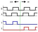
So if encoder A will be connected to external interrupt, then if you implement a state machine with A and B states, you will be able to measure not only speed (you can use a dedicated timer for this to measure the time between interrupts), but direction also (from state machine).

Take a look at the following link and pay attention at the incremental rotary encoder part (the gray coding for clockwise and counter-clockwise are actually the state machine for the two directions):

Rotary encoder - Wikipedia, the free encyclopedia


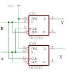
Anoter way is to use latches to make your life easier, but this will make your circuit more expensive.

66_1309413620.jpg

72_1309413620.jpg
 

what help do u want? is it software or hardware help? you can (of course) make frequency counter. I suggest you use A simple OP-AMP like LM324 having 4-QUAD INPUT. It makes you easier to debug the whole process.
 

I need help for software. I thing that I can't use interrupts because I have to take the signal from encoder to the A/D converter. So my question is do I need do debounce the signal I get from the A/D converter?
 

mladens said:
I have to take the signal from encoder to the A/D converter

What does this mean? Encoder produces two digital signals, A and B. Please elaborate or post the circuit.


mladens said:
do I need do debounce the signal

Yes, if we are talking about digital signals A and B from the encoder, you could use a non-inverting Schmitt buffer.


Regards,
Alexandros
 

What does this mean? Encoder produces two digital signals, A and B. Please elaborate or post the circuit.

Yes, if we are talking about digital signals A and B from the encoder, you could use a non-inverting Schmitt buffer.

This mean I get analog signal

I can't use any additional hardware, only software debounce (if I have to, but I don't have experience with optical encoder so I don't know do I need to do this)
 

mladens said:
This mean I get analog signal

I can't use any additional hardware, only software debounce

Maybe your board uses a frequency to voltage conversion.
Encoder is a fast changing input. You could debounce the analog signal, but I guess you must define zones of operation. For example 0.5-1.5V=low speed, 1.5 to 2.5=medium speed, 2.5 to 3.5=high speed. At the given example, if you counted 1.4V until now and suddenly you see a value of 1.7V, count it for some milliseconds first, and then consider it as a valid state changed (low speed became medium speed). Practically and depending on the application, maybe more zones are needed.
However, you could first try without debounce to see what happens and if you are not satisfied with the result, then insert the debounce code.


Hope that helped.
 

You should clarify which "analog" signal properties require to connect an AD converter to the encoder interface. As long as the signal swings beyond the VIL and VIH threshold values, it may be connected to digital IOs as well.

But if you would need to use ADC inputs, it's possible of course. You have to consider the ADC sampling and conversion time, so the maximum speed will be lower than with digital interfaces. Generally, the signals of a quadrature encoder don't need to be necessarily debounced. The decoding scheme involves a correct position count despite of bouncing signals. As you'll notice from th eliterature, a quadrature encoder signal is equivalent to a two bit gray counter, by design, only on eof two channels can bounce at a time, in turn, the counter position can be unsure by one position.

It should be considered, that some simplified decoder circuits may miss this elementary feature, e.g. decoders that are only processing one signal edge of the encoder. The circuit in post #3 is however working correctly, also with bouncing inputs. But it has the disadavantage of not cointing on each quadrature transition.

An example of a software quadrature decoder can be found e.g. in this recent thread:
https://www.edaboard.com/threads/216640/
 
Last edited:

The purpose of work is not clear. You want to measure speed or angle ?

If is only speed, a tachometer counter could be enought, but direction rotation information will be lost.
However if is angle, should consider Index pin, to resset account and correct some accumulated error, every time turns at position 'zero'.

PS : Some microcontrolers, like DSPIC30F60xx, have built-in quadrature decoder.

+++
 

Status
Not open for further replies.

Similar threads

Part and Inventory Search

Welcome to EDABoard.com

Sponsor

Back
Top