gonadgranny
Member level 4
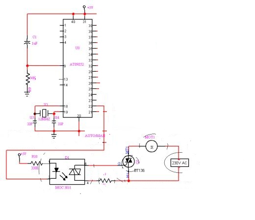
Hi. Would it be possible to use **broken link removed** (or any other suggestions) TRIAC to switch 40W bulbs connected to a 240V power supply using a 5v signal? (Arduino Microcontroller)
I am unaware of exactly how triacs function and know only that i want to simply be able to control my bulbs using my computer. I have tried relays but they are noisy and suffer from that irritating EMF kickback. ANy help would be very much appreciated.
Danny.
I am unaware of exactly how triacs function and know only that i want to simply be able to control my bulbs using my computer. I have tried relays but they are noisy and suffer from that irritating EMF kickback. ANy help would be very much appreciated.
Danny.