Continue to Site

Welcome to EDAboard.com

Welcome to our site! EDAboard.com is an international Electronics Discussion Forum focused on EDA software, circuits, schematics, books, theory, papers, asic, pld, 8051, DSP, Network, RF, Analog Design, PCB, Service Manuals... and a whole lot more! To participate you need to register. Registration is free. Click here to register now.

PIC experiment: (max) 15 keys using 4 pins, debounced, full IT controlled

Status
Not open for further replies.

zuisti

Advanced Member level 1
Joined
Jul 2, 2004
Messages
479
Helped
188
Reputation
376
Reaction score
183
Trophy points
1,323
Location
Hungary
Activity points
3,319
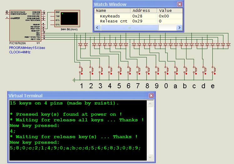
For decoding I'm using cheap Si diodes like 4148:


Key pressing is sensed via PORTB pin change IT, an the TIMER2 is used for a 20 msec debouncing.
Lookup table to define key return values.
Sensing depressed key(s) at power on.

Only one key can be pressed at a time (others are ignored), then it (all) must be released.

Written a small program to demonstrate the concept:
Attached a ZIP with the PROTON basic source, the HEX file and the DSN.

Sorry but I'm using also assembly snippets so for recompiling use the Proton 3506 (max).

What's your mind?
Greeting
zuisti
 

Attachments

  • Key15_zuisti_project.zip
    72.5 KB · Views: 172

What you describe is a passive binary encoder. The problem with this design, as you have observed, is that it is possible to create wrong numbers by holdng down more than one key at a time. You also need to pull the lines high so they read as '1' until one or more switches is pressed. You can use the internal pull-ups in the PIC but it would be wise to use external resistors as well.

Brian.
 

What you describe is a passive binary encoder
...
Brian
Hi Brian;
Thank you for valuable response.
Yes, this is a simple binary encoder (not a decoder, sorry for my mistake), plus a special IT routine, which resolves the problems mentioned by you (I think so ...).

The problem with this design, as you have observed, is that it is possible to create wrong numbers by holding down more than one key at a time.
True, but only if the second keystroke is occured in the small (20 msec) debouncing time window (this probability is small enough, right?). Then, the system is insensitive to the other button is pressed, and a new button will be accept only when all buttons released. Try it in Proteus!

You also need to pull the lines high so they read as '1' until one or more switches is pressed. You can use the internal pull-ups in the PIC
The attached program is using the internal pullups:
.... Clear OPTION_REG.7 ' RBPU, portb pullups on

but it would be wise to use external resistors as well.
In a noisy environment I also use external pull-up resistors directly on the encoder output lines, and small RC filters to defend the PIC inputs. In this case the internal pullups are disabled.

Thanks again.
Istvan
 

I do not have Proteus so I can not run your simulation. I found the code difficult to read, I always use MPLAB for assembly code or use a 'C' compiler for high level language. Does Proteus allow named bits in registers? I find lines like "If STATUS.2 = 1 Then " can be confusing, I think you are asking if the Z bit is set, doesn't Proteus allow something like "STATUS.Z" to make it more readable.
I would still use external pull-up resistors in preference to the internal ones. You may find the current source from the internal pull-ups is too weak to charge and discharge the input lines, especially if the cable to the keys is long or has a relatively high capacitance. I still think you may have problems with multiple keys as well, don't forget that if more than one key is pressed and there is key bounce, it is still possible to read the wrong number back if the bounce momentarily breaks the contact and makes it look as though the keys were released and re-pressed.

Brian.
 

good,and you must consider the cost first.
 

Status
Not open for further replies.

Part and Inventory Search

Welcome to EDABoard.com

Sponsor

Back
Top