nichocheng
Newbie level 3
Hi, all:
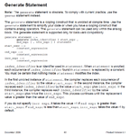
I need your help. I want to write verilog-A model about phase selector. The phase selector theory is: there are eight phase clock input, and the phase difference is 0.125*2*pi*Fref. I need to select one of them output.
When A=-1, the output is a phase that lag the current one
A=0, the output is current phase.
A=1, the output is a phase lead the current one by two
A=2, the output is a phase lead the current one by one.
I write the verilog-A model like this:
// VerilogA for USB20, PHASE_SELECT, veriloga
`include "constants.vams"
`include "disciplines.vams"
module PHASE_SELECT(P, IN0, IN1, IN2, IN3, OUT);
output OUT;
input [0:7] P;
input IN0, IN1, IN2, IN3;
voltage [0:7] P;
electrical IN0, IN1, IN2, IN3, OUT;
parameter real tdel = 0 from [0:inf);
parameter real trise = 0 from [0:inf);
parameter real tfall = 0 from [0:inf);
real IN;
integer i;
analog begin
@ ( initial_step ) begin
i=1;
IN = V(IN0) + 2*V(IN1) + 4*V(IN2) -8* V(IN3);
end
case (IN)
2: begin if (i-2>=0)
i= i-2;
else i= 8+i-2;
end
1: begin if (i-1>=0)
i= i-1;
else i= 8+i-1;
end
0: i=i;
-1: begin if (i+1<=7)
i= i+1;
else i=-8+i+1;
end
endcase
V(OUT) <+ transition(P, tdel, trise, tfall);
end
endmodule
Whatever I setup the IN0-IN3, the output is zero without any change. Can anyone help me? Thanks.
---------- Post added at 10:04 ---------- Previous post was at 09:32 ----------
My cadence version is 5.10.41, so I can not use "genvar" command.
Maybe it caused by this.