ksay2k
Newbie level 4
hi.
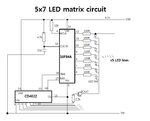
Please help me. I just built a LED matix circuit(attatched schematic below) with 16f84A and CD4022 counter. I tested some example hex files for movnig sign and I am not satisfied with the output because of an automatic reset which is unwanted. I dont know how to remove this....
What exact happen is that if the code of output is "HELLO" by assembly it shows H and E, not others, then starts again from the top automatically. It takes time about 3 seconds.
I tested other examples and found the same problem the 3 second-automatic reset.
I guess the MCLR or CLK problems, isn`t it? Or code...
As you can see the circuit, I used RC oscillator(4MHz) instead of crystal, the source from http://talkingelectronics.com/projects/5x7Display/Display_03_Construction-Part1.html I made a simpler circuit.
Thank you,

-CODE-
---------------------------------------------------------------------------------------------------------
Start ORG 0x00 ;This sets up the ports
BSF 03,5
MOVLW 00h
MOVWF 05h
MOVWF 06h
BCF 03,5
GOTO Run1
;Table1 holds the hex values for each column of LEDs
Table1 ADDWF 02h,1 ;Add W to Program Counter
RETLW 00h
RETLW 3Eh
RETLW 41h
RETLW 41h
RETLW 41h
RETLW 22h
RETLW 00h
RETLW 7Fh
RETLW 01h
RETLW 01h
RETLW 01h
RETLW 00h
RETLW 1Ch
RETLW 1Ch
RETLW 00h
RETLW 32h
RETLW 49h
RETLW 49h
RETLW 49h
RETLW 26h
RETLW 00h
RETLW 7Fh
RETLW 08h
RETLW 08h
RETLW 08h
RETLW 7Fh
RETLW 00h
RETLW 7Fh
RETLW 00h
RETLW 00h
RETLW 0FFh
Run1 CLRF 11h
CLRF 12h
CLRF 13h
CLRF 14h
CLRF 15h
MOVLW 00
MOVWF 22h
Run2 MOVLW 30h
MOVWF 19h
CALL Shift
INCF 26h,1
MOVF 26h,0
CALL Table1
MOVWF 15h
XORLW 0FFh
BTFSC 03,2
GOTO Run1
Run3 DECFSZ 19h,1
GOTO Run4
GOTO Run2
Run4 CALL Scan
GOTO Run3
Scan BSF 05,1 ;Reset 4017
NOP
BCF 05,1
MOVF 11h,0
MOVWF 06h
CALL DelD
MOVF 12h,0
MOVWF 06h
CALL DelD
MOVF 13h,0
MOVWF 06h
CALL DelD
MOVF 14h,0
MOVWF 06h
CALL DelD
MOVF 15h,0
MOVWF 06h
CALL DelD
RETURN
Shift MOVF 12h,0 ;Move file 12h to W
MOVWF 11h ;Move W to file 11h
MOVF 13h,0 ;Move file 13h to W
MOVWF 12h ;Move W to file 12h
MOVF 14h,0 ;Move file 14h to W
MOVWF 13h ;Move W to file 13h
MOVF 15h,0 ;Move file 15h to W
MOVWF 14h
RETURN
DelD DECFSZ 1Bh,1 ;Delay for viewing the
GOTO DelD ; column of LEDs
MOVLW 00h
MOVWF 06
Clk BSF 05,0 ;Clock the 4017 to
NOP ; the next output
BCF 05,0
RETURN
END
Please help me. I just built a LED matix circuit(attatched schematic below) with 16f84A and CD4022 counter. I tested some example hex files for movnig sign and I am not satisfied with the output because of an automatic reset which is unwanted. I dont know how to remove this....
What exact happen is that if the code of output is "HELLO" by assembly it shows H and E, not others, then starts again from the top automatically. It takes time about 3 seconds.
I tested other examples and found the same problem the 3 second-automatic reset.
I guess the MCLR or CLK problems, isn`t it? Or code...
As you can see the circuit, I used RC oscillator(4MHz) instead of crystal, the source from http://talkingelectronics.com/projects/5x7Display/Display_03_Construction-Part1.html I made a simpler circuit.
Thank you,

-CODE-
---------------------------------------------------------------------------------------------------------
Start ORG 0x00 ;This sets up the ports
BSF 03,5
MOVLW 00h
MOVWF 05h
MOVWF 06h
BCF 03,5
GOTO Run1
;Table1 holds the hex values for each column of LEDs
Table1 ADDWF 02h,1 ;Add W to Program Counter
RETLW 00h
RETLW 3Eh
RETLW 41h
RETLW 41h
RETLW 41h
RETLW 22h
RETLW 00h
RETLW 7Fh
RETLW 01h
RETLW 01h
RETLW 01h
RETLW 00h
RETLW 1Ch
RETLW 1Ch
RETLW 00h
RETLW 32h
RETLW 49h
RETLW 49h
RETLW 49h
RETLW 26h
RETLW 00h
RETLW 7Fh
RETLW 08h
RETLW 08h
RETLW 08h
RETLW 7Fh
RETLW 00h
RETLW 7Fh
RETLW 00h
RETLW 00h
RETLW 0FFh
Run1 CLRF 11h
CLRF 12h
CLRF 13h
CLRF 14h
CLRF 15h
MOVLW 00
MOVWF 22h
Run2 MOVLW 30h
MOVWF 19h
CALL Shift
INCF 26h,1
MOVF 26h,0
CALL Table1
MOVWF 15h
XORLW 0FFh
BTFSC 03,2
GOTO Run1
Run3 DECFSZ 19h,1
GOTO Run4
GOTO Run2
Run4 CALL Scan
GOTO Run3
Scan BSF 05,1 ;Reset 4017
NOP
BCF 05,1
MOVF 11h,0
MOVWF 06h
CALL DelD
MOVF 12h,0
MOVWF 06h
CALL DelD
MOVF 13h,0
MOVWF 06h
CALL DelD
MOVF 14h,0
MOVWF 06h
CALL DelD
MOVF 15h,0
MOVWF 06h
CALL DelD
RETURN
Shift MOVF 12h,0 ;Move file 12h to W
MOVWF 11h ;Move W to file 11h
MOVF 13h,0 ;Move file 13h to W
MOVWF 12h ;Move W to file 12h
MOVF 14h,0 ;Move file 14h to W
MOVWF 13h ;Move W to file 13h
MOVF 15h,0 ;Move file 15h to W
MOVWF 14h
RETURN
DelD DECFSZ 1Bh,1 ;Delay for viewing the
GOTO DelD ; column of LEDs
MOVLW 00h
MOVWF 06
Clk BSF 05,0 ;Clock the 4017 to
NOP ; the next output
BCF 05,0
RETURN
END
Last edited: