Welcome to our site! EDAboard.com is an international Electronics Discussion Forum focused on EDA software, circuits, schematics, books, theory, papers, asic, pld, 8051, DSP, Network, RF, Analog Design, PCB, Service Manuals... and a whole lot more! To participate you need to register. Registration is free. Click here to register now.
That circuit doesn't tell us anything about the load called "multiple logic ICs" but I'll assume that it is intentionally undefined if this is a general-purpose battery back-up supply.
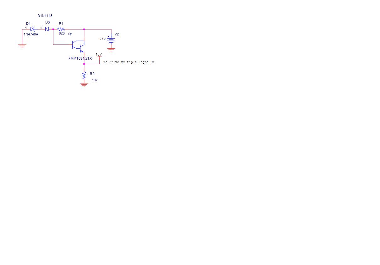
The use of a Darlington simply offers more available current into the "multiple logic ICs" than a single transistor would, from any reference current through the zenner. i.e. Its more efficient.
The zener diode will be able to provide a base current up to a certain limit (to be able to work properly and keep the specified voltage),
using a Darlington transistor the current gain of the two transistors is multiplied so the base current (from zener) will be a fraction of what it would be with only one transistor,
this way you can get higher output current (with the same base current) and more accurate zener voltage because the zener current will not have much variation when the output current changes.
This site uses cookies to help personalise content, tailor your experience and to keep you logged in if you register.
By continuing to use this site, you are consenting to our use of cookies.