Continue to Site

Welcome to EDAboard.com

Welcome to our site! EDAboard.com is an international Electronics Discussion Forum focused on EDA software, circuits, schematics, books, theory, papers, asic, pld, 8051, DSP, Network, RF, Analog Design, PCB, Service Manuals... and a whole lot more! To participate you need to register. Registration is free. Click here to register now.

[SOLVED] what's the difference between .coe file and the .mif file ?

Status
Not open for further replies.

blooz

Advanced Member level 2
Joined
Dec 29, 2010
Messages
560
Helped
121
Reputation
242
Reaction score
116
Trophy points
1,343
Location
India
Activity points
4,985
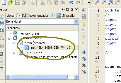
What is the basic difference between the .mif and .coe files ...When you generate a RAM block using the Xilinx Core genrator the .coe file is loaded ,but when simulating there appears a message saying that .mif not found .Is .coe file enough for implementing on FPGA and .mif for simulation .Could you please clarify the matter ?

here is the message

/////////////////////////
ISim M.53d (signature 0xb869381d)
This is a Full version of ISim.
Time resolution is 1 ps
Simulator is doing circuit initialization process.
Block Memory Generator CORE Generator module loading initial data...
WARNING: at 0 ps: file pram.mif could not be opened
////////////////////////////
 

Coefficient file (.coe) is used by synthesis tool to create memory initialization file (.mif). This file will be generated automatically once you invoke synthesis on your design.

Memory initialization file is used my simulation tool to generate results.
 
  • Like
Reactions: blooz

    blooz

    Points: 2
    Helpful Answer Positive Rating

    T Hima

    Points: 2
    Helpful Answer Positive Rating
Coefficient file (.coe) is used by synthesis tool to create memory initialization file (.mif). This file will be generated automatically once you invoke synthesis on your design.

Memory initialization file is used my simulation tool to generate results.

so mif has nothing to do with implementation we need only specify the .coe
 

so mif has nothing to do with implementation we need only specify the .coe

No, its other way around. Once you've mif in place you can throw away coe file (as long as content remains the same).

Here is quote from distributed memory datasheet:

The COE file provides a wrapper to allow the user to initialize memory contents. However, the MIF file
holds the actual binary data that is used to initialize the memory in the core and simulation models. The
MIF file consists of one line of text per memory location, the first line in the file corresponding to
address 0, the second line corresponding to address 1, and so on. The text on each line must be the initialization
value (MSB first) for the corresponding memory address in binary format, with exactly one
binary digit per bit of the memory’s width.

Hope this helps
 
  • Like
Reactions: blooz

    blooz

    Points: 2
    Helpful Answer Positive Rating
Some thing basically Wrong with my design .I can not see the .mif file in the program directory

something going wrong

the following synthesis message appears
////////////////////////////////////////////////
Xst:1901 - Instance U0/blk_mem_generator/valid.cstr/ramloop[0].ram.r/s3_init.ram/spram.ram in unit U0/blk_mem_generator/valid.cstr/ramloop[0].ram.r/s3_init.ram/spram.ram of type RAMB16_S36_S36 has been replaced by RAMB16
///////////////////////////////////////////////////////

---------- Post added at 13:08 ---------- Previous post was at 12:59 ----------

Here is the code used


First Generated a Ram module named 'pram' with width -12 and depth 16 using the core generator

then loaded the
.code file

Code:
 ;The data memory generated is 
 MEMORY_INITIALIZATION_RADIX=16;
 MEMORY_INITIALIZATION_VECTOR= F33,
3B2,
9B5,
7C6,
E42,
C31,
74D,
04B,
D24,
71D,
9D8,
CAB,
EBF,
BCF,
2D1,
67D;


then instantiated the memory in a top module ..
like

Code:
module top(clka,wea,addra,dina,douta);
//
input   clka;
input  [0 : 0] wea;
input  [3 : 0] addra;
input  [11 : 0] dina;
output  [11 : 0] douta;


pram pramt(
	.clka(clka),
	.wea(wea),
	.addra(addra),
	.dina(dina),
	.douta(douta));

endmodule
 

coe file and top module looks fine to me, can't locate source of your problem! Lets see what others have to say about it.

BTW, was the Core gen able to read the .coe file when you gave the file path?
 
  • Like
Reactions: blooz

    blooz

    Points: 2
    Helpful Answer Positive Rating
coe file and top module looks fine to me, can't locate source of your problem! Lets see what others have to say about it.

BTW, was the Core gen able to read the .coe file when you gave the file path?

Yes the coregen was able to read the .coe file ,and When I pressed Show button on the Window where it ask to load a .coe file all the memory elements were show correctly.

---------- Post added at 16:31 ---------- Previous post was at 16:17 ----------

Code:
WARNING:PhysDesignRules:812 - Dangling pin <DOA2> on
   block:<pramt/BU2/U0/blk_mem_generator/valid.cstr/ramloop[0].ram.r/s3_init.ram
   /spram.ram.A>:<RAMB16_RAMB16A>.
WARNING:PhysDesignRules:812 - Dangling pin <DOA3> on
   block:<pramt/BU2/U0/blk_mem_generator/valid.cstr/ramloop[0].ram.r/s3_init.ram
   /spram.ram.A>:<RAMB16_RAMB16A>.
WARNING:PhysDesignRules:812 - Dangling pin <DOA4> on
   block:<pramt/BU2/U0/blk_mem_generator/valid.cstr/ramloop[0].ram.r/s3_init.ram
   /spram.ram.A>:<RAMB16_RAMB16A>.
WARNING:PhysDesignRules:812 - Dangling pin <DOA5> on
   block:<pramt/BU2/U0/blk_mem_generator/valid.cstr/ramloop[0].ram.r/s3_init.ram
   /spram.ram.A>:<RAMB16_RAMB16A>.
WARNING:PhysDesignRules:812 - Dangling pin <DOA6> on
   block:<pramt/BU2/U0/blk_mem_generator/valid.cstr/ramloop[0].ram.r/s3_init.ram
   /spram.ram.A>:<RAMB16_RAMB16A>.
WARNING:PhysDesignRules:812 - Dangling pin <DOA7> on
   block:<pramt/BU2/U0/blk_mem_generator/valid.cstr/ramloop[0].ram.r/s3_init.ram
   /spram.ram.A>:<RAMB16_RAMB16A>.
WARNING:PhysDesignRules:812 - Dangling pin <DOA9> on
   block:<pramt/BU2/U0/blk_mem_generator/valid.cstr/ramloop[0].ram.r/s3_init.ram
Also this error message appear after map process .after synthesis
only an info is shown

Code:
Xst:1901 - Instance U0/blk_mem_generator/valid.cstr/ramloop[0].ram.r/s3_init.ram/spram.ram in unit U0/blk_mem_generator/valid.cstr/ramloop[0].ram.r/s3_init.ram/spram.ram of type RAMB16_S36_S36 has been replaced by RAMB16


---------- Post added at 17:29 ---------- Previous post was at 16:31 ----------

About that dangling pin warning the following explanation by xilinx seems fine but still I am not able to get correct result in simulation using Isim

h**p://www.xilinx.com/support/answers/31378.htm

---------- Post added at 19:19 ---------- Previous post was at 17:29 ----------

Also this strange Question mark appears

I could n't figure out the reason .

95_1300024121.jpg
 

That "?" in the screenshot means it couldn't find the specific file it needed for simulation. If you are using a generated core, maybe you need to look for the right file in the "ipcore_dir" directory. Presumably "pram.v" judging by your screenshot.

You then need to add that file to your project. Not 100% if that is the case, but it does look that way. I had to do something similar for a generated core.

hope that helps. :)
 
  • Like
Reactions: blooz

    blooz

    Points: 2
    Helpful Answer Positive Rating
.The major change adopted was a slight deviation from what i had done earlier

1.Create project
2.Use coregen to create the RAMblock,and Loaded a .Coe file (Earlier the .coe file was located outside the project directory ,this time it was copied to the project directory itself )
3.Added the .xco file to project
4.Then a top module was created as a testbench and instantiated the RAM core it
5. Simulated using Isim (Here an Important Thing I forgot in earlier Sessions .(trivial thing) Zoom has to be adjusted so that the time scale is proper for our test )
6.Everything Worked Fine

Next step is definitely to try the design in FPGA ...Hope it will work ..
 

Status
Not open for further replies.

Part and Inventory Search

Welcome to EDABoard.com

Sponsor

Back
Top