Continue to Site

Welcome to EDAboard.com

Welcome to our site! EDAboard.com is an international Electronics Discussion Forum focused on EDA software, circuits, schematics, books, theory, papers, asic, pld, 8051, DSP, Network, RF, Analog Design, PCB, Service Manuals... and a whole lot more! To participate you need to register. Registration is free. Click here to register now.

Light up a sigle led from a 8x8 led matrix

Status
Not open for further replies.

gabi68

Junior Member level 1
Joined
May 12, 2009
Messages
18
Helped
0
Reputation
0
Reaction score
0
Trophy points
1,281
Activity points
1,411
Hi,

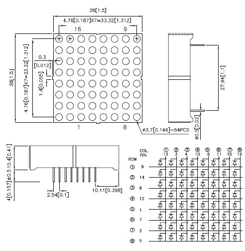
I need a piece of code in Mikrobasic to light up a single led (position on matrix it is not important) on a 8x8 matrix led, I will use a pic16F887. A schematic will awesome.
I will try to simulate that on Protues

Thank you
Gabi
 

Anyone?? Tahmid....
 

It's not that hard to write the code yourself.
The LED-Matrix as a column index and a row index. Setting both indices, will turning a specific LED on.

Hope this helps.
 

....to light up a single led (position on matrix it is not important) on a 8x8 matrix led...
Hi;
Attached a 8x8 led matrix schematic as an example. It's a row side common anode typ:
44_1299055030.jpg

Now you can lit any LED of 64, for example the top left on picture:
-connect pin 13 to GND
-apply a current limiting resistor (say 330 Ohm) in series to pin 9
-connect the resistor to an output pin of your uC.
The LED will lit if the port pin goes to high (+5v).
 

Still, even for you it is simple for it is almost imposible. Can I have a little piece of code (in mikrobasic will be awesome)? Thanks for schematic but I need a little schematic with whole circuit (MCU and Led matrix), if you dont mind?

Regards
Gabi
 

Hi,

I only need a piece of code in Mikrobasic to see how it works. So, anyone....

rgds
Gabi
 

Here is the schematics:
1- Connect LED-Matrix Row pins to PortA of your controller.
2- Connect LED-Matrix Column pins to PORTB of your controller through a 220Ohm or 330Ohm resistors.

The code:
'Turn on LED 4 in column 4
Code:
TrisA=0
TrisB=0
PortA = 0x08
PortB=0xF7
 

Thank you. It is working. Now I need to move that leds, but that it is another matter.

Gabi
 

Use the same concept and change the values of PORTA and PORTB.
 

Can you be more specific, please? I don't want to mix oranges with apples.
 

Can you be more specific, please? I don't want to mix oranges with apples.
You now have the trick, change the values of PORTA and PORTB with any sequence you want.
Example:
Code:
	PORTA=0x01;
        PORTB=0xFE
	while(1)
	{
		for(i=0; i<7; i++)
		{
			Output <<= 1;
			PORTA = ~Output;
			PORTB = Output;
			Time_Delay(50);
		}
		for(i=7; i>0; i--)
		{
			Output >>= 1;
			PORTA = ~Output;
			PORTB = Output;
			Time_Delay(50);
		}
	}
 

Hi,

Thank you for codebut I use Mikrobasic and I belive that was written in C. Can you cooment that a little bit or better translate in Mikrobasic.

Thank you for your time
Gabi
 

I am not familiar with C, but I think in that code it is a mistake. How that for statement it is incremented if variable i is not there, Can you post a working code in Mikrobasic?

Thank you
Gabi
 

Just change the syntax of the "For Loop" to match that of the MikroBasic and, remove all the "Semi-colons". The rest of the code remains as is.
 

Hi,

seadolphine2000 - translated code look like this
Code:
dim i, output as byte

main:
TrisA=0
TrisB=0
PORTA=0x01
PORTB=0xFE
	while 1

		for i=0 to 7


			Output = output <<1
			PORTA = not Output
			PORTB = Output
			Delay_ms 500
			next i

		for i=7 to 0


			Output =output >> 1
			PORTA = not Output
			PORTB = Output
                        Delay_ms 500
                         next i
                   wend

end.
On the Proteus simulation first 6 columns are up and stay like that. What that little piece of code suppose to do?

zuisti - I will have a look. One question - can you look at that mikrobasic code and tell me if it is translated ok.

Thank you
Gabi
 

Output = output <<1
Initialize Output with 0x01

This is a rotating light pattern. The LEDs will lit in ascending sequence then, when all are lit, they will be off one by one.
 

Hi,

I make output=0x01 but the seqvence it is different. The ledlit up diagonally and that's all....

Regards
Gabi
 

Hi,

I make output=0x01 but the seqvence it is different. The ledlit up diagonally and that's all....

Regards
Gabi

If you don't know how it works (or figure it out) you'll never really make the right LEDs light up. Random attempts and guessing will just make you waste more time.

Look at the pictures/diagrams that someone already posted. Draw it on a piece of paper, and draw which leds you want lit up. Then determine which of the output pins need to be high and which need to be low to get the current flowing in the right direction and light up a LED.

If you want the LED to move, draw 2-3 steps of the moving sequence on the paper and then determine how the output pins need to change to make that moving sequence. That will let you determine the 'math' behind the animation.
 

I will never understand why can you post a solution. I try to learn, but it is hard without example.
 

Status
Not open for further replies.

Part and Inventory Search

Welcome to EDABoard.com

Sponsor

Back
Top