Continue to Site

Welcome to EDAboard.com

Welcome to our site! EDAboard.com is an international Electronics Discussion Forum focused on EDA software, circuits, schematics, books, theory, papers, asic, pld, 8051, DSP, Network, RF, Analog Design, PCB, Service Manuals... and a whole lot more! To participate you need to register. Registration is free. Click here to register now.

ultra broadband buffer amplifier schematic needed

Status
Not open for further replies.

neazoi

Advanced Member level 6
Joined
Jan 5, 2008
Messages
4,119
Helped
13
Reputation
26
Reaction score
15
Trophy points
1,318
Location
Greece
Activity points
36,918
Hello,
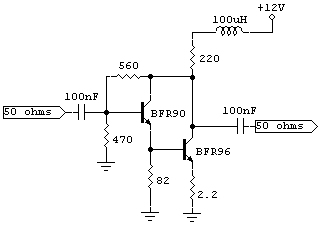
I have a 3KHz-50MHz signal generator and I would like to amplify it's 2.3mw output to +7dbm. I am looking for a broadband amplifier that can do this. The mmics like mar2 mar6 etc have a max output of 1-2mw tho these are not good I think. Any other solution?
 

An RF broadband lab. amplifier : ZHL-6A from Minicircuits and put some attenuators at the output
 
  • Like
Reactions: neazoi

    neazoi

    Points: 2
    Helpful Answer Positive Rating
This is a good solution, but I was thinking of a schematic to build.
 

The attached schematic is the equivalent what generally have inside a silicon MMICs. The gain is about 20dB and the frequency range starts from very low frequencies up to hundreds of MHz.
The 220 ohms bias resistor may need adjustments when using different type of transistors and Vcc voltages.
11_1296043527.jpg
 
Excellent!
I have both types of transistors, I will try it and let you know.
 

The attached schematic is the equivalent what generally have inside a silicon MMICs. The gain is about 20dB and the frequency range starts from very low frequencies up to hundreds of MHz.
The 220 ohms bias resistor may need adjustments when using different type of transistors and Vcc voltages.
11_1296043527.jpg

I have tried it with a bfr91 instead of a bfr90 and without the 100uh. I placed a 0.1uf shunt at this place.
It amplifie ok on 12v. On 7v the amplification is not much affected. Since I have a stable 7V voltage, can I use this instead? Do I need to make any changes for 7v?
 

If you don't use 100uH, you'd better increase the 220 ohms to more than 250ohms, and ensure you get needed power level at the output. Surely need 100nF at +7V.
 

I have built several amplifiers along the lines of the schematic given by vphone; they work well.

You should reduce the 220 ohm bias resistor for 7v Vcc; without doing any calculations I would guess that a value of about 22 - 47 ohms would work for 7v.

The RF choke becomes more necessary as the value of the bias resistor is reduced.

The Vcc line is/should be bypassed via capacitor(s) to ground (as you have done but not shown in vphone's diagram as it is elementary).

So the bias resistor is, for RF, effectively across/shunting the output load; this degrades the impedance match.

The choke adds large series Z to the bias resistor and therefore reduces the shunting effect; the resistor/choke junction should not have a bypass capacitor for this reason.

As jayce said, extra gain & power output will allow use of attenuation, particularly at the output; this will ensure that the output is well-matched to the load.

I have used this technique to increase the output and improve the output impedance match in two signal generators just as you are doing; it works very well; here is one built "ugly" style on the output BNC connector and using a very similar circuit to that given by vphone;

https://i46.tinypic.com/2iia1is.jpg
 
Last edited:
  • Like
Reactions: neazoi

    neazoi

    Points: 2
    Helpful Answer Positive Rating
I have built several amplifiers along the lines of the schematic given by vphone; they work well.

You should reduce the 220 ohm bias resistor for 7v Vcc; without doing any calculations I would guess that a value of about 22 - 47 ohms would work for 7v.

https://i46.tinypic.com/2iia1is.jpg

I have altered the 220R to 43R and placed the choke instead of the capacitor.. Amplification is more now but the choke and the resistor (and the transistors) get hot now. It now draws 60mA more.Is this normal?
 

The circuit will draw more current as the resistor is reduced; that is normal; you could increase the resistance if you wish.

You say " ... 60mA more ..."; do you mean a total of 60 mA or an additional 60 mA?

A total of 60mA should be OK for those transistors; more current (within the limitations of the transistors used) makes a "stronger" amplifier.

Re the heating; either your resistor and your choke are not able to dissipate the power (so use higher-current/wattage devices) or you have oscillation.

The transistors are really too "good" for use in your frequency range; they have an Ft of 6 GHz.

A rule-of-thumb is that Ft should be about ten times the maximum frequency required; this would imply transistors with Ft of 500 MHz.

Using very-high-Ft devices invites oscillations; I would use 2N5109, 2N5179, 2N3866 (or similar devices with Ft around 1 GHz) in your application.

Spectrum analysis would confirm; even a radio receiver can be used to find oscillations.

Only a few days ago I built a 40dB gain amplifier using two GALI-39 MMICs; when I tested it it was generating a "comb" of signals at about 220 MHz intervals up into the GHz range. The reason was that I had just clipped test leads to the input & output; when I installed proper RF connectors (SMA) the oscillations disappeared.
 
  • Like
Reactions: neazoi

    neazoi

    Points: 2
    Helpful Answer Positive Rating
Must use the choke in series with the bias resistor, to increase the load bias reactance at working frequency, otherwise you lose RF power on the bias resistor.
There is a rule, the reactance of the bias circuit (resistor + choke reactance) should be at least 10 times higher than load impedance (which is 50 ohms).
This circuit can go down to about 6V Vcc, but have to lower the bias resistor in concordance.
 
  • Like
Reactions: neazoi

    neazoi

    Points: 2
    Helpful Answer Positive Rating
Nevertheless it works ok, I would like a better constant current circuit to be constructed for this amplifier. I have used simple two transistors constant current source on this circuit (for which the amplifier is intended) **broken link removed** at the amplifier stage. But this current source sinks current (connected between the amplifier and the ground.
How should I connect it to source current (connected between the VCC and the discrete mmic amplifier)?
I would like to stick with transistors for this design.


How about this one? **broken link removed**
It is the same as the one I have used. It just connects the load between this and the GND

- - - Updated - - -


How about this one? http://www.vidisonic.com/2008/07/10/current-limiting-circuit/
It is the same as the one I have used. It just connects the load between this and the GND
 

Any simple current-limiter should be OK.
 

Ok I made it. Here is the complete schematic
**broken link removed**
It works without any difference in the output waveform. The only difference is the little bit increased output which was expected and it is desirable. One of the two 2n2222 transistors in the curent sources gets a quite hot, but not so hot so that is needs a heatsink. If I try to increase the sense resistor the output level drops much, so I think I have supplied enough current to the amplifiers with a 20R.
Output power is about +9dbm, enough to drive an sbl-1 mixer. I may add a third cascated stage to bring the output to about +17dbm, to drive an sbl-1H mixer for lower insertion loss and noise...
 
Last edited:

Status
Not open for further replies.

Part and Inventory Search

Welcome to EDABoard.com

Sponsor

Back
Top