crankler
Junior Member level 2
Do you mean if i remove the gate voltage, the triac will turn off in the next current zero crossing?
About the RC snubber, what is its purpose? does it look like this:
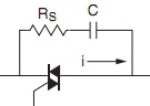
About the RC snubber, what is its purpose? does it look like this:
