Continue to Site

Welcome to EDAboard.com

Welcome to our site! EDAboard.com is an international Electronics Discussion Forum focused on EDA software, circuits, schematics, books, theory, papers, asic, pld, 8051, DSP, Network, RF, Analog Design, PCB, Service Manuals... and a whole lot more! To participate you need to register. Registration is free. Click here to register now.

[SOLVED] Learning PIC Programming

Status
Not open for further replies.
Hi,
For simulator, I recommend Proteus although it's not free or cheap either.
As for DC motor control and analogue stuff, first thing: read the datasheet and google for reference manual. Then come to the forums on the questions you have. Plus, go to the Help menu in the mikroC compiler and check the ADC and PWM libraries.

Hope this helps.
Tahmid.
 

here we go...
this how u going to connect mclr


from your diagram in proteus, may I know what is the name of the 4 pins switch call in the proteus?

and one more question is from the below threat have the pin that have to connect is 1 and 3 or 1 and 4 why do you connect the pin 1 and 4 , is that your connection is correct?
 

Hi, guys I am also catching something in this thred, that's very good job tahmid keep on.
 

i suggesting to use PROTEUS ISIS for simulation..it have the library that include thousand of component including motor..
 
Hello,
I've done a program to run an LCD display,JHD162A.
I've written the program,and also simulated it with Proteus,n it is working.
However,after burning it to PIC it is not working !!
What may be the reason ?? Please help !!
 

Have you set your configuration bits correctly?
 

I've written the program in MikroC,so it is done automatically,isn't it ??n also it is working on simulator !


char text[] = "Nitish";

sbit LCD_RS at RB0_bit;
sbit LCD_EN at RB2_bit;
sbit LCD_D7 at RC7_bit;
sbit LCD_D6 at RC6_bit;
sbit LCD_D5 at RC5_bit;
sbit LCD_D4 at RC4_bit;

sbit LCD_RS_Direction at TRISB0_bit;
sbit LCD_EN_Direction at TRISB2_bit;
sbit LCD_D7_Direction at TRISC7_bit;
sbit LCD_D6_Direction at TRISC6_bit;
sbit LCD_D5_Direction at TRISC5_bit;
sbit LCD_D4_Direction at TRISC4_bit;

void main() {
TRISB=0;
TRISC=0;
PORTB=0xFF;
PORTC=0xFF;
TRISB=0;
TRISC=0;

Lcd_Init(); // Initialize Lcd
Lcd_Cmd(_LCD_CLEAR); // Clear display
Lcd_Cmd(_LCD_CURSOR_OFF); // Turn cursor off
Lcd_Out(1,1, "Hello !!!"); // Print text to Lcd, 1st row, 1st column
Lcd_Out(2,1, text); // Print text to Lcd, 2nd row, 2nd column

Delay_1sec();
Delay_1sec();
}
 
Last edited:

Click on the add an image button under the reply box. then browse for the image to upload it.


Also how do I check whether the LCD is itself working or not ??
 

Attachments

  • LCD.zip
    907 bytes · Views: 83
Last edited:

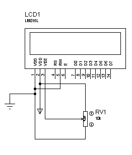
Hello,I had not connected the Vee to ground ! now after connecting Vee directly to ground I see all faint black squares or sometimes only the second row black,however no text !! What do I do ?? Thanks for the help provided yet !
 

Hi,
Vee is for adjusting the contrast of the LCD. Connect a pot to the pin like this and adjust it until you see something (also, you forgot to connect MCLR to +5v):
56_1292828437.png


Hope this helps.
Tahmid.
 
Hi,
Vee is for adjusting the contrast of the LCD. Connect a pot to the pin like this and adjust it until you see something (also, you forgot to connect MCLR to +5v):
56_1292828437.png


Hope this helps.
Tahmid.

Hey,thanks !! Ill try soon,don't have a potentiometer right now !n I'd connected the MCLR to Vcc,although that wasn't there in the schematic !
 

Hi,
Vee is for adjusting the contrast of the LCD. Connect a pot to the pin like this and adjust it until you see something (also, you forgot to connect MCLR to +5v):
56_1292828437.png


Hope this helps.
Tahmid.

Hey,thanks !! Its working !! Thanks a lot Tahmid !
One more thing that I want to ask is that,suppose I want to write a program which displays scrolling text on LCD and at the same time runs a motor,or does something else,then how to write it in a program,i.e. simultaneous processing of two things ??
And yes now my next project will be running a motor with L293D !
I have checked the pin configuration,and datasheet !! Will upload the schematic as soon it is ready,so that you check it !
 

Hi,
Have the LCD working in the main code and run the PWM through interrupts. Like:
Code:
ISR
   1. Check if interrupt is associated with PWM
   2. Update CCPR1L with required value for required duty cycle
   3. Clear flag
   4. Return
end ISR

main code block:
   * Initialize everything required, eg ports, port directions, timer (TMR2 - for PWM), PWM (CCP1CON, CCPR1L)
   1. Set PWM period through PR2
   2. Set PWM duty cycle through CCPR1L
   3. Make sure you initialized TMR2 and CCP1CON properly
   4. Enable CCP1 interrupt
   5. Set GIE
   6. Set PEIE
   7. Start TMR2
   8. Do LCD stuff
end main code block

I hope you can use this bit to write the code. If you get stuck, I can help you with the coding.

Hope this helps.
Tahmid.

---------- Post added at 16:42 ---------- Previous post was at 16:41 ----------

You can use the PWM library which would make everything much easier. I'll try to post a sample code later.

---------- Post added at 16:43 ---------- Previous post was at 16:42 ----------

You can also achieve this without interrupt. I'll see if I can post a code to show how.

As a first step,can I not just run the motor without PWM ??
Later on I can go for PWM ! Frankly,I don't anything about PWM !

Also,I have to learn using interrupts ! How do I go about this ?
Also,when are interrupts required ?
 
Last edited:

Hi,
Yes you can run motor without PWM. Just set the pin high and use a transistor or MOSFET to drive the motor.
When you are doing one thing, you can not make the PIC do something else. This is when the interrupt is needed - for multitasking. You can keep on performing one job until an interrupt occurs, then in the interrupt service routine (ISR), you carry out another set of tasks as quickly as possible, then go back to your main program for what you were doing.

Hope this helps.
Tahmid.
 

Hello,I have a DC Geared motor.I have written the following program so that it rotates in one direction for some time and then changes direction.

Code:
void main() 
{
  while(1)
  {
   TRISB=0;
   PORTB=0b10000000;    //Motor moves in one direction
   Delay_ms(10000);
   PORTB=0b01000000;    //Motor moves in the opposite direction
   Delay_ms(10000);
  }
}

However,the motor doesn't work as expected.Nonetheless,I get the desired voltage difference at the output !What may be the problem ??
I have used a L293D to drive the motor !
 

Status
Not open for further replies.

Similar threads

Part and Inventory Search

Welcome to EDABoard.com

Sponsor

Back
Top