Continue to Site

Welcome to EDAboard.com

Welcome to our site! EDAboard.com is an international Electronics Discussion Forum focused on EDA software, circuits, schematics, books, theory, papers, asic, pld, 8051, DSP, Network, RF, Analog Design, PCB, Service Manuals... and a whole lot more! To participate you need to register. Registration is free. Click here to register now.

Problem with light dimmer circuit with MOC3021

Status
Not open for further replies.

hammooooody

Newbie level 6
Joined
Mar 24, 2010
Messages
11
Helped
0
Reputation
0
Reaction score
0
Trophy points
1,281
Activity points
1,369
i'm working on a light dimmer circuit for light bulb (not an inductive load yet),
I've programmed an AVR to generate a PWM to the MOC3021 which is connected to a TRIAC bt136. I got interesting result from oscilloscope tests, The generated signal PWM is synchronized with the Zero Crossing signal and everything else is fine..

The problem is the bulb lights up to full even if i set the PWM to 20% or 40% duty cycle. I tried to measure the MOC3021's output waveform, but i got a weird shaped signal. what should i expect it to be? any ideas to fix this problem?

I've been told that i wouldn't notice the bulb getting dimmer since it is resistive and heats up and stuff like that even if 20% of the sinusoidal signal is passing through to it. is that true?

Thank you,
 

help me with MOC3021

Hi,
Why PWM? You're supposed to be using phase angle control.
When you set PWM duty cycle at 20%, the output is high for the first 2ms and low for 8ms. But as soon as the output goes high, the MOC3021 fires the triac, which gets latched (on) until the next zero crossing.
Take any duty cycle and you'll see that the lamp will always light upto full brightness.
What you have to do is, if you need 20% brightness:
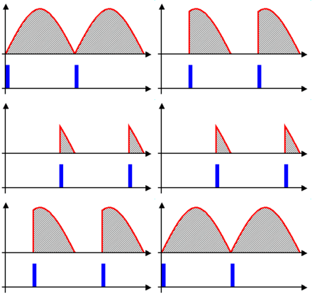
Half period is 10ms. So, your output needs to be on for 20% first half, then 20% second half. So, that means 80% off, this 80% is "cut" through phase control. Wait for 80% of the half-time, ie, 8ms and THEN send a high pulse to the MOC for about 100us and then turn the pulse low. Repeat this for the second half as well, and THEN you will get 20% brightness.

I've been told that i wouldn't notice the bulb getting dimmer since it is resistive and heats up and stuff like that even if 20% of the sinusoidal signal is passing through to it. is that true?

False. You'll be able to see the bulb dim gradually from 0 to full brightness and vice versa.

Hint: Don't use PWM, instead set the timer in CTC mode, set OCRx such that compare match occurs every 100us. Then count how much you need to wait on a scale of 0 to 100. 80 for 80% off.
Increment a counter every compare event. After it reaches 80, then fire the output. Wait 100us and then clear the output. Repeat for second half cycle and you have phase angle control.

https://en.wikipedia.org/wiki/Phase_fired_controllers

15_1277448873.gif


Hope this helps.
Tahmid.
 
Re: help me with MOC3021

@ "Tahmid" Thanks for the excellent explanation even dummies can understand clearly. We are proud to have you as an member in EDA board. Keep it up.
Cheers
 

Re: help me with MOC3021

dear tahmid

you have helped me in many of the occasion,but i have doubt about what

you have explained, actualy as per my knowledge and experience,if the duty cycle

is 20% ,than pulse amplitude will be high at around last par of pulse, so that

moc 3041 will give firing pulse at the end part of ac half cycle, if the percentage of duty cycle increases,leading edge of pulse will advance toward 0 mili second, if we calculate from 0 mili second to 10 mili second
even as per my experience, moc 3023 is beter than moc 3041, because moc 3041 requires 15 mA, while moc 3043 requires 5 mA to turn ON,

you can opt moc 3052 is also good alernative, because o/p voltage of moc 3052

is 600 v capacity,while o/p voltage of moc 3041 triac is 400 vcapacity

venus electronics
 

Re: help me with MOC3021

venuselectronics said:
you have explained, actualy as per my knowledge and experience,if the duty cycle

is 20% ,than pulse amplitude will be high at around last par of pulse, so that

moc 3041 will give firing pulse at the end part of ac half cycle, if the percentage of duty cycle increases,leading edge of pulse will advance toward 0 mili second, if we calculate from 0 mili second to 10 mili second

Hi,
I think you misunderstood what I said. I meant exactly what you just said: it has to be at the last part. When I talked about firing at the first part, I was referring to traditional PWM applied to MOSFETs and BJTs, in which circumstance, 20% duty cycle refers to the starting part.

I hope I made myself clear.
Tahmid.
 

Re: help me with MOC3021

dear tahmid

in second part of your explanation , you had explained the matter, what ever i have explained

i had read half part only

venus electronics
 

Re: help me with MOC3021

Thanks for the replies .. I appreciate your help so much :)

Here are some photos of the oscilloscope .. first two photos taken in reference to the input signal (transformer's output) and others to the ZCD signal.. The one in blue color represents the AVR output signal ... sorry the photos are bad quality glossiness and stuff but you can read the number.

Now my question is, what am i doing wrong? should i (for 20% brightness) start with 80% off (8ms) then the on part follows (2ms) ? i don't see any difference ..

Thank you,
Hammoooody
 

help me with MOC3021

dear tahmeed: do u have triac firing angle control cktry diagram and explanation too..
i understand what u want to say about firing of traic is that if we need 20% duty cycle then inspite of firing triac at beginning of zero crossing we must fire it 20% before the ending of that cycle..
do u have any diagram that shows how to connect moc321 and bta-16.. also how can i detect origin of my input signal??
plz help me

Added after 2 minutes:

if any one else have answer to my question plz help me as soon as possible... actually i m doing project on runway lightning control .. so if any one has idea about microcontroller based constant current regulation (M.C.C.R) for air feild lightning plz help me..
 

help me with MOC3021

Hello,
You have to know that thyristors (SCR/Triac, etc) get latched once you give 1 to base. So until the next zero crossing, the thyristor will be latched.
So, when you start with 2ms and then micro sends 0 for 8ms, even for that 8ms, the thyristor is on. That's why you need 8ms off and then approximately 100us on. In this case, for first 8ms thyristor is off. Then, when you give 1 for 100us the thyristor is on until next zero crossing which is approximately 2ms.

I hope I made this clear.
What you have done will always yield 100% brightness.

Hope this helps.
Tahmid.

Added after 5 minutes:

Hi teerath,
Take a look at this:
40_1277663481.jpg

Hope this helps.
Tahmid.
 
help me with MOC3021

It helped SO MUCH!! Thanks a Billion Tahmid :)
 

Re: help me with MOC3021

hey guyz help me to with i did the same thng as tamid said but my buld flickers..m jst doin simple 20% brigthness for nw to test...it does decrese the brightness but it flickers.

#include <REG2051.H>
int i,j,a;
sbit moc=P3^7;
void delay();
void delay(int x)
{
for(i=0;i<100;i++)
for(j=0;j<x;j++)
;
}

void isr(void) interrupt 0
{

moc=1; ///bulb off for 8ms
delay(8);
moc=0; /// bulb on for 2ms
delay(2);
moc=1;
delay(8);
moc=0;
delay(2);

}
void main()
{
EX0 = 1; // Enable EX0 Interrupt
EA = 1; // Enable Global Interrupt Flag
while(1)
{
;
}

}


NOTE= i am using moc3041 and connect in such a way that wen i give low pulse i.e '0' it fires..buld on..
 

Status
Not open for further replies.

Part and Inventory Search

Welcome to EDABoard.com

Sponsor

Back
Top