Continue to Site

Welcome to EDAboard.com

Welcome to our site! EDAboard.com is an international Electronics Discussion Forum focused on EDA software, circuits, schematics, books, theory, papers, asic, pld, 8051, DSP, Network, RF, Analog Design, PCB, Service Manuals... and a whole lot more! To participate you need to register. Registration is free. Click here to register now.

PIC cannot communicate with computer via RS232

Status
Not open for further replies.

cheppe32

Newbie level 1
Joined
Jan 9, 2010
Messages
1
Helped
0
Reputation
0
Reaction score
0
Trophy points
1,281
Location
Tanzania
Activity points
1,289
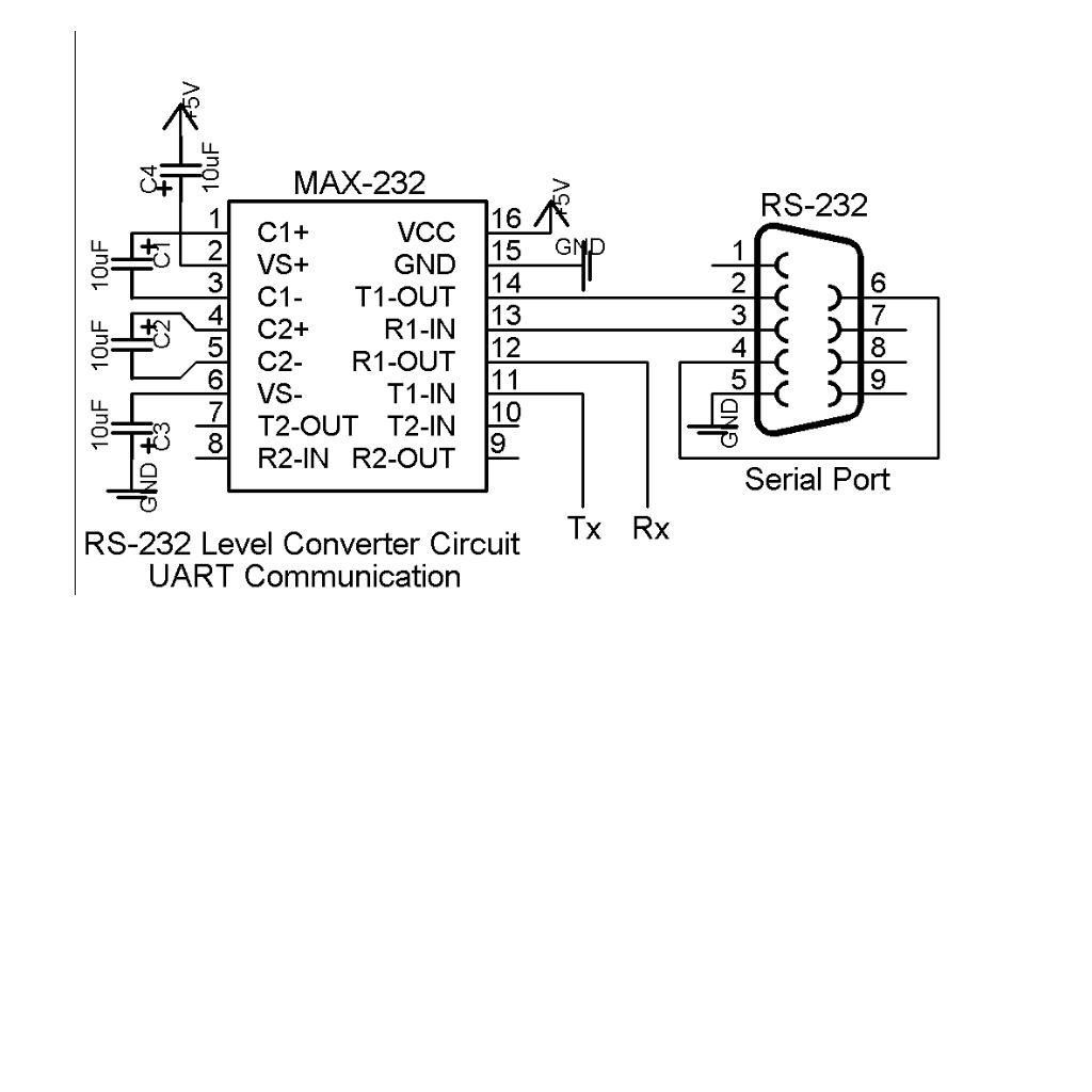
Hi everyone, I am doing a project on home automation system as my final year project. But my mikroc code cannot communicate with PC, when simulate it with proteus it easly communicate with hyperterminal but giving a warning about Configuration bit word. i dont know if thats the reason it cant exchange data with PC. the following is my source code and i am using PIC 16F876A UART connection with RS232 converter.... I'm not a gud programmer nyway!!!


Code:
char cellcommand;


void main() {
  TRISB = 0x00;
  PORTB = 0x00;
  UART1_Init(9600);
  
  Delay_ms(2000);
  
// Endless loop
  while (1) {
  
// If data is received,
   if (UART1_Data_Ready()==1) {
       
//   read the received data,
     cellcommand = UART1_Read();
     Delay_ms(10);
     
//   and send data via UART
     UART1_Write(cellcommand);
       PORTB.F4=1;
       PORTB.F5=0;
       Delay_ms(1000);
    }
    else if(UART1_Data_Ready()==0){
       PORTB.F5=1;
       PORTB.F4=0;
       Delay_ms(10);
       PORTB.F5=0;
       Delay_ms(10);
       }
//Selecting outputs depending on the recived character
     switch(cellcommand){
       case 'A': (PORTB.F0=1)&(PORTB.F1=0);
                 break;
       case 'B': (PORTB.F0=1)&(PORTB.F1=1);
                 break;
       case 'C': (PORTB.F0=0)&(PORTB.F1=0);
                 break;
       case 'D': (PORTB.F2=1)&(PORTB.F3=0);
                 break;
       case 'E': (PORTB.F2=1)&(PORTB.F3=1);
                 break;
       case 'F': (PORTB.F2=0)&(PORTB.F3=0);
                 break;
       case 'p': (PORTB.F0=1)&(PORTB.F1=0)&(PORTB.F2=1)&(PORTB.F3=0);
                 break;
       case 'q': (PORTB=0x00);
                 break;
    }

}
}
 

Check ur connection.
uart3.jpg
 

    cheppe32

    Points: 2
    Helpful Answer Positive Rating
Your code seems to be ok. It should show the different configurations of the Port Output depending on the key inputs.

Just make sure the configuration word is correct. Sometimes it matters. (For ex: If you use the Internal oscillator, but configured to use a External Crystal in the config word will halt the operation of the PIC.

My advise is to debug in two easy steps.

1) Use a LED Blink like simple program, upload and see if the PIC is working
2) Use the UART1_Write(UART1_Read()) in somewhere in the interrupt routing and check if it feedbacks to the terminal where you are sending the data.

There you go, you can easily figure where the problem is.
 

Status
Not open for further replies.

Similar threads

Part and Inventory Search

Welcome to EDABoard.com

Sponsor

Back
Top