mirzaahmad
Newbie level 2
- Joined
- Mar 27, 2010
- Messages
- 2
- Helped
- 0
- Reputation
- 0
- Reaction score
- 0
- Trophy points
- 1,281
- Location
- multan,pakistan
- Activity points
- 1,309
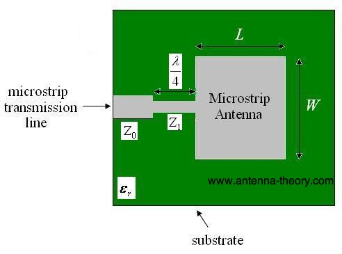
i wanna design a microstrip patch antenna with following specifications
Patch:-
Length=35.014mm
Width=45.33mm
Transmission line:-
length=20.392mm
width=2.911
Frequency band:-
1.930-1.990Ghz
with center frequency at 1.960Ghz
but now m unable to understand electrical length n characteristic impedence of line in degrees...
i dont know what does these terms mean?
kindly do help me...