Continue to Site

Welcome to EDAboard.com

Welcome to our site! EDAboard.com is an international Electronics Discussion Forum focused on EDA software, circuits, schematics, books, theory, papers, asic, pld, 8051, DSP, Network, RF, Analog Design, PCB, Service Manuals... and a whole lot more! To participate you need to register. Registration is free. Click here to register now.

Scale and Shifting Op-amp voltages

Status
Not open for further replies.

niiayi22

Newbie level 4
Joined
Mar 1, 2010
Messages
6
Helped
0
Reputation
0
Reaction score
0
Trophy points
1,281
Location
UK
Activity points
1,342
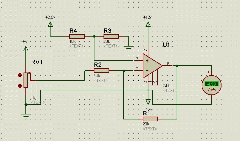
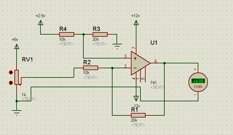
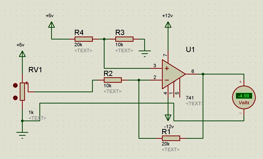
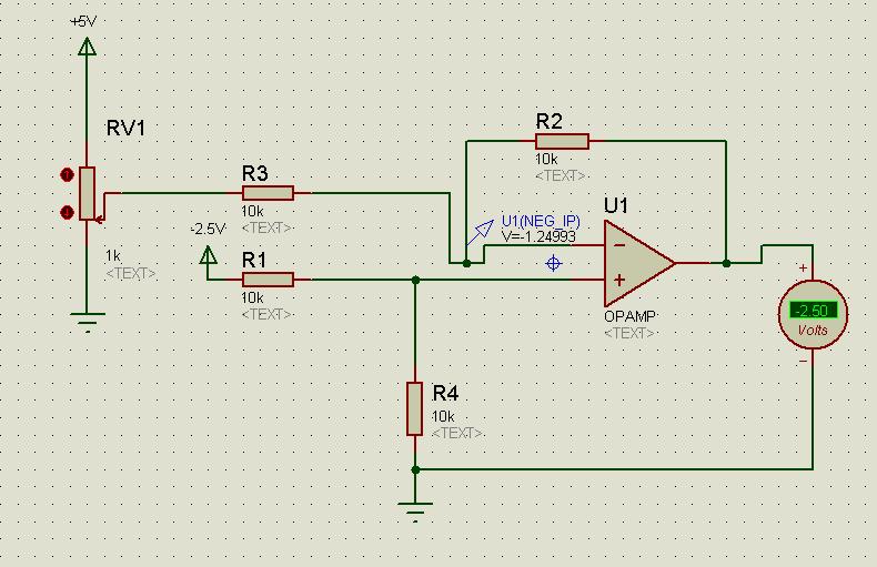
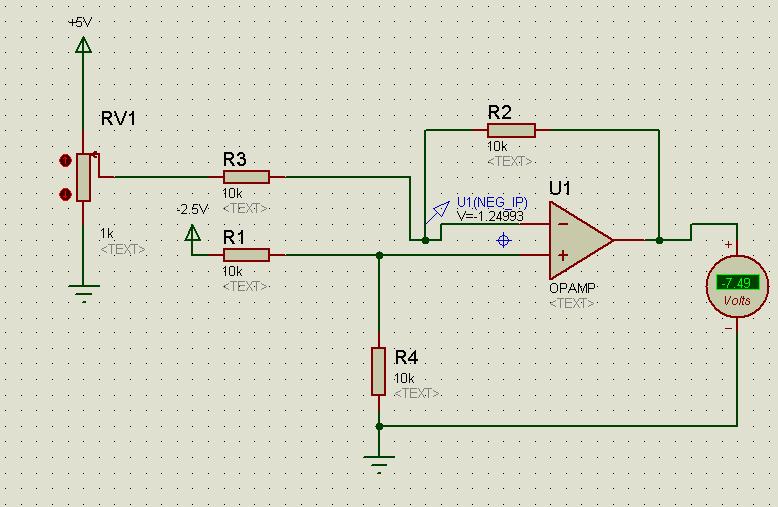
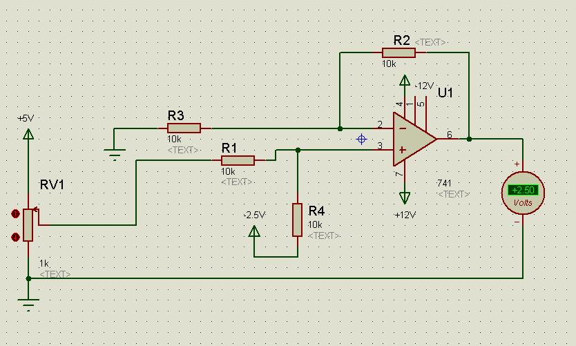
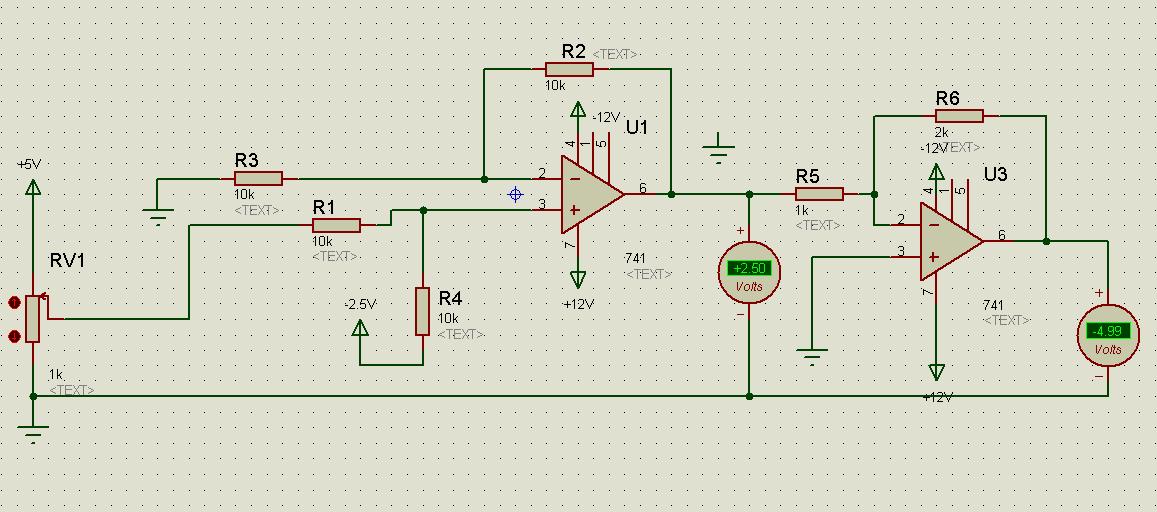
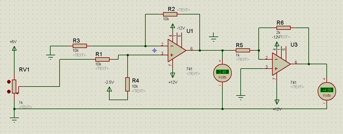
Hi. I need help Shifting a voltage from 0->5v to -2.5v->+2.5v. I've managed to use an op-amp circuit to scale and shift +/-5v to 0->4.3v using the inverting and non-inverting equation together, but i'm not sure how to do this one (despite the fact that it's probably easier)

I'm using a PIC18F2455 to output an analogue voltage to my motor set via D/A conversion. I can only output a range of 0v to +5v (because PICs cannot ouput negative voltages) which will move the motor from 0rpm to maxrpm clockwise. For anti clockwise i need to use negative voltage.

If i do this correctly i assume that i'll only be able to apply half the max speed in either directon? (+2.5v and -2.5v)
If so would i be able to scale 0-5v to +/-5v for Max speed?

Many thanks

PS: Motor is a MS15 DC Motor which is attached to its own board with multiple sensors (pot, tacho, gray code, slotted disk etc) so cannot edit the circuit for the motor..it simply requires -5v for max rpm counter clockwise and vice versa
 

The easiest way is to use two op amp circuits in series. The first op amp circuit would be an inverting op amp with a gain of -1. At the input you would have a -2.5 volt constant DC signal thru one resistor, and you would sum this with the 0 to +5 volt signal you already have. The output o that op amp would be +2.5 to -2.5 volts.

You would then send that signal to another inverting op amp, but this one with a gain of -2 and a high current output. That would convert the voltage swing back to -5 to +5.

By inverting op amp circuit, I mean one like below. First op amp would have R1, R2, and Rf = 10K. In the second op amp, there is no V2 input, and R1=1K and R2=2K. In either case, leave off Rg. You will need at least +/- 9V DC power supply rails.
 

Thanks for the reply. I'm using ISIS 7 to simulate the design. So far for the first op-amp i have got the 0v outputting -2.5v (correct) but -7.5v at +5v input (should be +2.5v). I know my resistor values are not correct but not really sure how to work them out for this type of op_amp arrangement. By the way do i have the inputs the right way round? (-2.5v into + terminal)

Thanks!

Prpgress so far:


Added after 8 minutes:

Realised you gave the resistor vals so thanks for that...

Added after 1 hours:

Awesome! managed to do it...didnt have the Vin terminals connected in the right place. It should look like this....


Now my range is changed to +/-2.5v (from 0-5v)...i shall now try the second stage: scaling this to +/- 5v for full motor range


Thanks for your help! saved me valuable time on this! :-D

Added after 27 minutes:

Hi there. Finished the 2nd part: I've now got:
input +5v --->+2.5v--->-5v output

input 0v--->-2.5v---->+5v ouput

Doesnt really matter that the polarity changed, this just means that to move the motor clockwise means sending negative voltage as opposed to positive.


Thanks again for putting me in the right direction..i can now build my circuit with confidence!
 

I may have missed the point here, but surely it can be done with one opamp? I assume you are just wanting to shift 0-5V to 5V to -5V.

Keith
 

Attachments

  • diffamp_1657.pdf
    5.5 KB · Views: 238

Your totally right! Thanks a bunch, saved even more time soldering tommorow :)
Here's a simulation of what u suggested..0v to 5v converted to -/+5v


I think it can be done without a 2.5V source as well with the correct resistors. I need to check but I can post it tomorrow if you interested.

Keith
 

Yeah that would be great thanks.
Otherwise i was thinking about how to get a clean 2.5v from my 5v and 12v supplies. Small errors in that voltage seem to affect the output voltage quite a bit. Particulary if i put in less than 2.5v, i start to go over the 5v i need for the motor to reach max speed. would want to try avoid that :)
 

Connect R4 to 5V and swap the values for R4 & R3.
 

Bingo! thanks again. Much appreciated! Would have taken me over a week to get this point on my own! :)

Picture below to show it works. When POT is at the other end, the voltage is the same but positive..


How would one scale an audio signal input to 0-5V :?:
 

Whatever a CD player or the audio output of a PC would be. It is my understanding that this would be in the range of ±1.55V. And I am only interested in the positive cycles, so with a Schottky diode in series with the input, I am talking about 0-1.35V in and 0-4.98V out (I can live with a little slop). Also, can a circuit be powered by just 5VDC (i.e., a single sided supply)?
 

i have output variable the [1.825 - 3.125] and i need transform in [0 - 5]
you can help me ?
 

Status
Not open for further replies.

Similar threads

Part and Inventory Search

Welcome to EDABoard.com

Sponsor

Back
Top