Continue to Site

Welcome to EDAboard.com

Welcome to our site! EDAboard.com is an international Electronics Discussion Forum focused on EDA software, circuits, schematics, books, theory, papers, asic, pld, 8051, DSP, Network, RF, Analog Design, PCB, Service Manuals... and a whole lot more! To participate you need to register. Registration is free. Click here to register now.

Pure Sine Wave Inverter output filter design

Status
Not open for further replies.

jeffreywong

Junior Member level 1
Joined
Jul 14, 2009
Messages
15
Helped
5
Reputation
8
Reaction score
3
Trophy points
1,283
Location
north, kampar
Activity points
1,449
inverter output filter

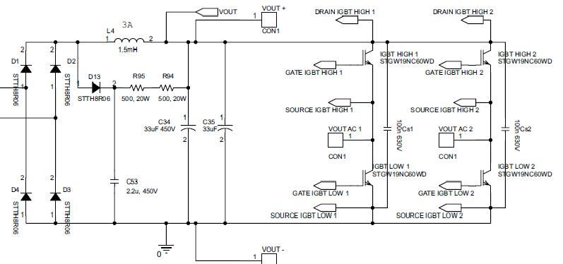
Im design a inverter, for hoosehold equipment, but the output of inverter needed a filter.
1) The ouput filter better using 2 order filter that is LCLC filter is better?
2) How to calculate the value of filter that I use ?
If u have the output filter design, plese send to my email- jeffrey_5097@yahoo.com


Thanks...........
 

inverter filter design

What do you want to filtering? RF noise? or swithing frequency?
 

hi
am designing a sine wave inverter i just put LC filter it's working but am not satisfied with this because my one of the output wire is directly connected from the switch to the load. do anyone have a suggestion to improve my filter design and is there any problem if i use LC filter. since am new to this i need some inputs

Thanks
 

I would split the inductor into two inductors. Then put one inductor on each output leg. If there is need for isolaiton, I would then put a transformer on the output.
 

you really need 2 filters. one that is taylored to remove the noise related to the switching frequency of the inverter and the other is very high frequency (maybe 1Meg) which removes the noise generated from the actual switch event (going from 0V to 350V in 1 micro second as an example). use a simple 2nd order L-C filter set at 10x your fundamental frequency (but 10x lower than your switching frequency). then the next stage is the very high frequency, usually this is just a bead filter or maybe a high-mue torroid surrounding the phase wires.

Mr.Cool
 
and what about the losses due to filters?
 

what about it? if you're filtering that much noise that it is creating heat problems then you must have had a LOT OF NOISE and would have had more serious problems anyway. inductors are easy to cool and a capacitors are difficult but you can buy good quality foil cap (WIMA) and you'll be OK.

anyway, yes the inductor 3-phase differential noise can get hot and yes it can be and must be cooled. but you know most of the energy is in the low frequency "noise", at multiples of the fundamental, not switching frequency. the source for this is the deadtime of your inverter (and also the bemf of motor load). so if you solve this (and it has already been solved) then your cooling needs will drop a lot.

Mr.Cool
 

Dear jeffrey
Hi
Are you referring to a 50 HZ sine wave inverter ? if yes , are you using SPWM method ? If you give me more informations i can help you as well to design it .
Best Wishes
Goldsmith
 

Dear jeffrey
Hi
Are you referring to a 50 HZ sine wave inverter ? if yes , are you using SPWM method ? If you give me more informations i can help you as well to design it .
Best Wishes
Goldsmith

Hi Goldsmith, I was searching through EDAboard for solution to SPWM inverter output filter design when I came across your post. Please, your answer will help me as well.
I want to design a 50Hz fundamental frequency sine wave inverter and I am using SPWM mehtod at a switching frequency of 50Khz for an output power of 250Watts. Please, will you walk me through the design and selection of Magnetics for the Output filter inductor.
Thanks
Hi babinton
Of course i want help you . but where is exactly your problem ? is that about the topology ? or perhaps elements selection ?
Best Wishes
Goldsmith
 

Dear Babinton,

Study this application note, hope this will help you.
 

Attachments

  • 24 to 350v CONVERTER.pdf
    3.1 MB · Views: 454

Hi babinton
Of course i want help you . but where is exactly your problem ? is that about the topology ? or perhaps elements selection ?
Best Wishes
Goldsmith

DC-AC inverter output lowpass filter inductor(magnetic design) for filtering out the High frequency Harmonics in the SPWM output waveforms.
regards
 

Dear Babinton,

Study this application note, hope this will help you.
This is not a "pure sine wave" design. There is no filter inductor in AC output. Modified sine wave does not require output filter choke. The inductor used is with DC rectification path.
4487607000_1360048349.jpg
 

Status
Not open for further replies.

Similar threads

Part and Inventory Search

Welcome to EDABoard.com

Sponsor

Back
Top