Continue to Site

Welcome to EDAboard.com

Welcome to our site! EDAboard.com is an international Electronics Discussion Forum focused on EDA software, circuits, schematics, books, theory, papers, asic, pld, 8051, DSP, Network, RF, Analog Design, PCB, Service Manuals... and a whole lot more! To participate you need to register. Registration is free. Click here to register now.

[SOLVED] pic16f72 sinewave inverter with asm codes. not working.

Status
Not open for further replies.
sudipmuk said:
He had my schematic and pcb was also ready with him. Only thing he didn't have was the hex file. And after cracking the password to my zip file , he now has everthing including the asm code..
Sorry to know about that.
sudipmuk said:
I cannot post the full project in the forum, if you want i can post the sinewave generation part(schematic and asm) in the forum.
.
You are most welcome to post anything that will be benificial to the electronic fraternity. Good luck.
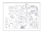
 

hi friends this is the project of pic 16f72 quasi sinewave inverter scematic. please post pic16f72 sinewave inverter hex file. i will post here my hex file ok. mr;sudipmuk really i don't know who r u. what ever happened with you is not ok. please dont mistake me i am not that shiddu ok. i am editing my post becouse of mr;pranams' word ok. if you have the hex file please post here. thanks in advance.
 

Attachments

  • 12v-500va_1550.jpg
    12v-500va_1550.jpg
    790.6 KB · Views: 1,305
hi sudip...
i am joined to your community.
first thing i want to share with mr/pranam
pranam he was giving me the password protected file. that is truth. and he was agread that is the currect file. and one more thing he was giving me that file you posted in the forum. how i am get these things you know. just i did one tricks that is comparison of file property. and file created date both are same. and his demo hex code there is some changes in charging re-start function. i will post here that file also in next time. what ever words using with me that all are false. and your pic 16f72 based inverter with giving asm file working but there is some modifications required. that also i will post in next time. but , i have 2 type squre wave inverter technology. that is for my own purpose. and i cant share here. i am bying these things from chenni. if he give me the currect file i will definatly give my 2 type technologies to sudip.

i am sorry mr. shiddu i am also in karnataka. i will give you my details in next time. again i am sorry mr.shiddu these all are happened due to my side. and i am not seing these theads every day. ondu kelsa madu pranam kottiro file nalli mosfet channels ge 220e rasisters sersu. matte check change over relay driving transistor. ok cheers... i will done these things with my own experience. please do not continue your old trikcs mr sudip.
 

shiddu.b said:
hi sudip...i am joined to your community. first thing i want to share with mr/pranam .pranam he was giving me the password protected file. that is truth. but i can't fix the file it is impossible also. i am just say i get your password. and he was agread that is the currect file. and one more thing he was giving me that file you posted in the forum. how i am get these things you know. just i did one tricks that is comparison of file property. and file created date both are same. and his demo hex code there is some changes in charging re-start function. i will post here that file also in next time. what ever words using with me that all are false. and your pic 16f72 based inverter with giving asm file working but there is some modifications required. that also i will post in next time. but , i have 2 type squre wave inverter technology. that is for my own purpose. and i cant share here. i am bying these things from chenni. if he give me the currect file i will definatly give my 2 type technologies to sudip.

i am sorry mr. shiddu i am also in karnataka. i will give you my details in next time. again i am sorry mr.shiddu these all are happened due to my side. and i am not seing these theads every day. ondu kelsa madu pranam kottiro file nalli mosfet channels ge 220e rasisters sersu. matte check change over relay driving transistor. ok cheers... i will done these things with my own experience. please do not continue your old trikcs mr sudip.
You may be anyone..but do not prank here. Be civil. Behave well. You have joined today on 04th Jan 10 and you are posting regrets for all that have beyond this date. what does it mean? You can mention your loaction a HUBLI but your IP is traced as from Bangalore, same as "shiddu".
Ok..this topic about you people is clear now, and arguements will not continue further hereon. Anyone starting it again will be Banned for ever.
Any replies and querries to the original topic may continue and are welcome...
 

can anyone share a 500 watt sine wave inverter schematics with PCB layout, component layout and source codes if any in your collection which you have tested and worked. i il be greatful
. Regards.
 

Me too, I am so intersted to get the code for 16F72
 

dear friends

do not waste your time in begging circuits here ( i have done long back) but dint get ne responses my frank advice 2 all is pay money n get gud circuits , coz i have paid 60k n got 2 gud sinewave inverter designs along with source code , beautiful working
i a have posted this becoz no one will be ready 2 share anything for free
regts
 
Dear Rashmi30,
I can send you hex file which should work with your pic 16f72 based sine wave inverter. But before that can I have a look at your PCB art work.
Thanking you
Mohamad.
 
hi friends...
pic 16f72 based sinewave inverter is working. but there is sum modifications required. i.e the relay driving transistor polarity and connections.
and one more thing is in given asm file having only single step charger, switching freq is 5.6khz, that is not suitable for long life. if any body having multi step charger with 16khz switching frequency. please post here and im having many typy pcb layouts. i will post those here.
 
Ok...here is a snap of an inverter board built with PIC16F72. Sorry i dont have the schemtaic. If any one offers me the code which will go with this board, i am ready to purchase it. Even i'll go for the technology too if some one has it.
Cheers
 
pranam77 said:
Ok...here is a snap of an inverter board built with PIC16F72. Sorry i dont have the schemtaic. If any one offers me the code which will go with this board, i am ready to purchase it. Even i'll go for the technology too if some one has it.
Cheers
if u can give the schematic i can build u code for it. atleast give the functions of the pins of PIC , like which pins are controlling the mosfets , is it active-high or actiive-low .. etc.

Added after 9 minutes:

sahu said:
dear sudipmuk plz send the password for technology.zip
Dear venkey3777 & sahu
Sorry for the late reply . But i donot have the password for that file technology.zip

And one more thing , saleem.shek has written a great thing. No one is going to give u a commercial design for free.
 

The asm code for the 16F72 is not working, kindy recheck the code and reupload it .. It will be great if someone can rewrite the code in C language or kindly upload the working HEX file .. Here is the link of which I am talking about .. This ASM code is not valid and cannot be build, contains lots of errors. Please post the HEX file soon ..

Thanks in advance :D
 

sudipmuk said:
if u can give the schematic i can build u code for it. atleast give the functions of the pins of PIC , like which pins are controlling the mosfets , is it active-high or actiive-low .. etc.

Sudip..thanks for the reply..actually the said board is very much liked by one of my friend and wants its technology or the code. He got it from some inverter and the schematic is not available. As per his observations, this is the only board he found which controls the charging voltage in steps. Mean for a discharged battery, it will deliver 10 amps, later it will reduce to 8-6 and so on and go to trickle charge when fully charged. Rest all features are same as other brands. If you can do it, i can send you traced pin details of the same.
Cheers

bhai_kaju said:
The asm code for the 16F72 is not working, kindy recheck the code and reupload it .. It will be great if someone can rewrite the code in C language or kindly upload the working HEX file .. Here is the link of which I am talking about .. This ASM code is not valid and cannot be build, contains lots of errors. Please post the HEX file soon .. Thanks in advance :D
And...you'll make money...nice Idea:idea::idea::idea::D...Why dont you buy a technology of the same and share it here for the benefit of all memebers?...
 

The code is not working so its useless anyway. I was just asking for the code to work so that everyone of us could test it. I am not into any business with microcontrollers, just want to expand my knowledge of programming .. You misinterpret my intention :-(
 

bhai_kaju said:
The code is not working so its useless anyway. I was just asking for the code to work so that everyone of us could test it. I am not into any business with microcontrollers, just want to expand my knowledge of programming .. You misinterpret my intention :-(
Ok...you may correct the code or share any other codes you have relating to the same subject. Cheers
 

pranam77, the board you shown that is also problem. i know the board manufacturer very well. abnormal sound coming from transformer when mains a/c
down to180v or lower.
 
jayananda said:
pranam77, the board you shown that is also problem. i know the board manufacturer very well. abnormal sound coming from transformer when mains a/c down to180v or lower.
Ok...thanks jaynanda for the reply and the info. Actually the said board is verified and liked by one of my friend and wants the technology for the same. Hope he has not tried it to the level you mentioned. Hope the boards manufacturer/ designer is too a EDAboard member. I am in contact with him on my personal mail ID. Cheers
 

Hi Pranam77
The sound which jayananda mentioned is due to the improper timing of Triac/SCR which is a problem in the code and very minimum chance of a hardware fault.
I have done step mode charging for one of my client . If you can give me the pin details , i can try to build the code.
I hope only giving the hex code will be enough .
 

Sudip...at present i am in contact with the designer of the board given in my post. As per my conversation with him, that board is his commercial product and he is not selling that layout. Instead, he promised me to give the same schematic in other board layout. The working will be the same but the PCB layout will be different. Regarding the sound mentioned by Jaynanda, is truely created by the firing of the Triac used for charging, and now it is rectified. ..Anyways,,thanks for the input...Cheers..
 

Status
Not open for further replies.

Similar threads

Part and Inventory Search

Welcome to EDABoard.com

Sponsor

Back
Top