Continue to Site

Welcome to EDAboard.com

Welcome to our site! EDAboard.com is an international Electronics Discussion Forum focused on EDA software, circuits, schematics, books, theory, papers, asic, pld, 8051, DSP, Network, RF, Analog Design, PCB, Service Manuals... and a whole lot more! To participate you need to register. Registration is free. Click here to register now.

Need help for design directional coupler for swr meter

Status
Not open for further replies.

ganzz_84

Newbie level 2
Joined
May 23, 2009
Messages
2
Helped
0
Reputation
0
Reaction score
0
Trophy points
1,281
Activity points
1,293
build swr meter

Hi...all,

I want to build swr meter for vhf band using pcb fr4,substrate thickness 1,24mm
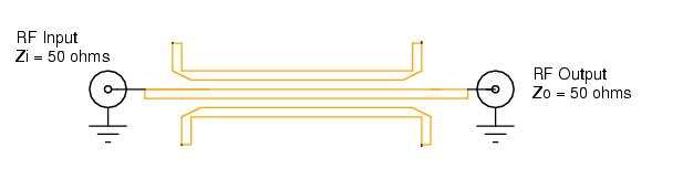
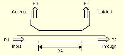
i have some pic of directional coupler design..and confuse about it...

my question is
1. can some one give me some formula to design ??
2. what the difference of two pic ?? are same design ??


82_1243307043.jpg
 

swr directional coupler

what the difference of two pic
The difference is what you see. The small picture shows a 6-port coupler, the large a standard 4-port. SWR meters are often using a 6-port coupler, because it's directivity is nearly unaffected by mismatching of the detector outputs.
 

rf swr coupler

can u or some one give some formula or reference to design 6 port coupler ???
 

Check out Mongia's book on couplers. Very good.

Might I suggest you look at a dual directional coupler instead? These are commonly implemented for SWR measurements.
 

Status
Not open for further replies.

Part and Inventory Search

Welcome to EDABoard.com

Sponsor

Back
Top