Continue to Site

Welcome to EDAboard.com

Welcome to our site! EDAboard.com is an international Electronics Discussion Forum focused on EDA software, circuits, schematics, books, theory, papers, asic, pld, 8051, DSP, Network, RF, Analog Design, PCB, Service Manuals... and a whole lot more! To participate you need to register. Registration is free. Click here to register now.

Pulse Width Modulator modification

Status
Not open for further replies.

EnergyGuy

Newbie level 2
Joined
Dec 1, 2008
Messages
2
Helped
0
Reputation
0
Reaction score
0
Trophy points
1,281
Activity points
1,308


This seems to be a better place to put this and is my second post for this information.
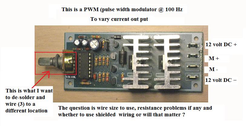
I have a PWM to control the current going to a 12volt DC hydrogen generator up to 30 amps. The PWM has a 10K variable pot on the board with three connection points (soldered to board) (see illustration). I want to remove this pot and wire it inside the vehicle and leave the board under the hood where I can put a heat sink and fan on it to cool it. I will be running it at from 15-20 amps but as the generator heats up so will the current draw go up so I want to be able to reduce it from inside the vehicle. Can I use plain 22 gauge wire twisted or shielded? Not sure about the resistance increase either or gauge of wire to use. The wiring and pot will be approximately 8 feet from the board (physically about 5 feet but to route it around and to the control box I’ll put it in, it will be about 8-10 feet of 3 wires).
Thank you in advance for any assistance on this small project!
Energy Guy
 

I could comment if I knew what chip it's using. Can you give that detail?Sometimes moving a pot like that is very tricky, other times it's no big deal. You should not be concerned with the wire resistance, which is very low compared to the pot, but with noise pickup in those 8ft of wire.
 

I would definitely suggest shielded cable. If one side of the pot is connected to GND, then that terminal would be connected to the shield. If none of the pot terminals are at GND, then you need a three conductor cable with a shield.
From the picture, I would guess that your PWM chip is running as an analog oscillator with the frequency determined by the pot setting. Since the pot is part of the analog oscillator, its leads are sensitive to noise. Shielded cable, series inductors and ceramic by-pass capacitors are probably required.
In an analog system, moving this pot is not as easy as it appears. Any noise coupled into the pot terminals could cause secondary oscillations and glitches in the PWM output.
 

Status
Not open for further replies.

Part and Inventory Search

Welcome to EDABoard.com

Sponsor

Back
Top