Continue to Site

Welcome to EDAboard.com

Welcome to our site! EDAboard.com is an international Electronics Discussion Forum focused on EDA software, circuits, schematics, books, theory, papers, asic, pld, 8051, DSP, Network, RF, Analog Design, PCB, Service Manuals... and a whole lot more! To participate you need to register. Registration is free. Click here to register now.

Drive Multiple Stepper Motors through PC

Status
Not open for further replies.

bhavrana

Newbie level 3
Joined
Sep 6, 2007
Messages
3
Helped
0
Reputation
0
Reaction score
0
Trophy points
1,281
Activity points
1,300
bipolar stepper circuit

Need Help Plz help me out regarding this..I have to submit minor project for this i've thought of Robotic arm.
It requires 5 stepper motors. So Plz help me out.. :cry:
 

multiple stepper motors parallel

please help me out in driving atleast one stepper motor..plz
 

bhavrana said:
please help me out in driving atleast one stepper motor..plz

do you have the required hardware for controlling the stepper without a pc ?
 

hmmm ...
One of my very old project use a PC to control stepper ...
Here is the link :
**broken link removed**

As i say ... is ... old ;)
Click the English Flag if you dont understand French .... he he he ...
Use it as example , if you want control bigger motors then just add
power transistors or Mosfet to the outputs.

Cya.
 

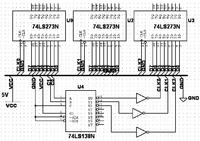
You need 4 lines for each stepper. You would need 3 8 bit latches like a 74373 or 374. You would enable all latches to keep the data on the output lines. You would then use two pins to control an addressable latch or 1 to 4 encoder. This would allow you to select an output pin from the addressable latch to toggle it high and low. Each pin would go to a 374 latch strobe (clock) pin. The data on the parallel port data port would then be strobed or latched as outputs on the 374. Of course the latched data would have to go to a darlington or a mosfet to power the steppers.
 

see this link for driving stepper motor
**broken link removed**

But you can drive only 3 such steppers without any expansion. Which is your stepper? bipolar or unipolar

read this link for parallel port expansion
**broken link removed**

If it is a bipolar stepper circuit will change


Bibin John
www.bibinjohn.tk
 

Here is the simplest and cheapest solution I can think of for you.
It uses D0-D7 and C0 and C1 of the pport.

Set C0 and C1 both high on the parallel port.
All of the latches CLK pins will go low
Put the data you want written to a latch on the data lines.
Strobe the CLK input of the latch you want to write to by
- putting its address on C1 and C0: 00 or 01 or 10.
The CLK pin on that latch will go high.
- then set C0 and C1 both high again. The selected latches
CLK pin will go low again.
The data has been strobed onto the output pins of that latch by the
low to high transition.

- If you can find a 74XX238 chip, you don't need to use the inverters
that need to be used for the 138 decoder.
- You can't use more than three latches with this scheme. But it will
drive 6 steppers.
- Remember to put the outputs to a darlington or a mosfet.
- You need a .dll that will let you write to the port but there are lots out there
and there have been lots of threads on this board on how to do it.


Added after 2 hours 58 minutes:

A unipolar stepper motor will have four lines to coils which will each
have an identical resistance. The other line will be power
Put an ohmmeter on two lines. A reading of 2 resistances will mean you
have two coil lines. A reading of one resistance will mean you have
one coil line and the power line. You should be able to figure out your coil lines
and power line from this.
Apply power to the power line and ground each line, one at a time, until the shaft moves. Call this line 1. Try another line, if it moves CW, call it 2. If it moves CCW, call it 4. If it doesn't move at all call it 3.

To move the stepper just sequence the pins 1-2-3-4. To reverse, just go 4-3-2-1.
This is full stepping. To half-step go 1,2 - 2,3 - 3,4 - 4,1 and repeat. To half-step
the opposite direction just reverse it. To halt, stop sequencing.
For timing I would use the queryperformancecounter() WIN32 API call. If a stepper has 12 degrees/step then you need to step 30 times for one revolution. To get 60 rpm you need 1800 steps per minute, about 33.3 ms/step. For half-stepping the times would be 16.67 ms.
I have stepped 2 motors and the timing was perfect. so a computer might be able to handle 5 at a time.

Added:
Actaully, if you connected C2 to the 138's C pin, you could select up to seven latches. Just set C2 high when you set both C0 and C1 high to set all CLKs low.
 

Status
Not open for further replies.

Part and Inventory Search

Welcome to EDABoard.com

Sponsor

Back
Top