Continue to Site

Welcome to EDAboard.com

Welcome to our site! EDAboard.com is an international Electronics Discussion Forum focused on EDA software, circuits, schematics, books, theory, papers, asic, pld, 8051, DSP, Network, RF, Analog Design, PCB, Service Manuals... and a whole lot more! To participate you need to register. Registration is free. Click here to register now.

Is there a workaround for power supply not local with an optoisolator?

Status
Not open for further replies.

doncarlosalbatros

Full Member level 2
Joined
Nov 26, 2016
Messages
143
Helped
1
Reputation
2
Reaction score
1
Trophy points
18
Activity points
1,758
Is there a workaround for power supply not local with receiver input?

I'm stuck with an issue.. A 0-5V 33Hz pulse train need to be interfaced with an optocoupler 4N46 before it reaches to a DAQ input. This is need to block common mode EMI which introduces noise at this DAQ's input.

Untitled.png

If you look at my drawing, if I interface an optocoupler between the Arduino and the DAQ input, I have to use a separate power supply for the opto output 5V Vcc in the diagram. That is fine but I will not be able to locate the power supply close to the DAQ input. I mean after the optocoupler output there will be a two wire cable max 100cm long upto the point receiving input.

Since the supply for the opto is not at the receiving board, I'm afraid to introduce a new ground loop. DAQ is a bit high 100cm above and I'm not sure it has 5V supply built in. Here is a photo you can see the DAQ boards are stacked and the supplies are on the ground of the big enclosure:
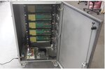
d2.jpg

Is there any workaround for this problem? I can make the opto board close to the DAQ input, but if the DAQ has no supply the power supply for the opto can only be on the ground of the big enclosure. I can use STP wires or purchase any kind of supply but don't know what could be the proper approach.

Thanks in advance.
 
Last edited:

Re: Is there a workaround for power supply not local with receiver input?

I'm stuck with an issue.. A 0-5V 33Hz pulse train need to be interfaced with an optocoupler 4N46 before it reaches to a DAQ input. This is need to block common mode EMI which introduces noise at this DAQ's input.

View attachment 150312

If you look at my drawing, if I interface an optocoupler between the Arduino and the DAQ input, I have to use a separate power supply for the opto output 5V Vcc in the diagram. That is fine but I will not be able to locate the power supply close to the DAQ input. I mean after the optocoupler output there will be a two wire cable max 100cm long upto the point receiving input.

Since the supply for the opto is not at the receiving board, I'm afraid to introduce a new ground loop. DAQ is a bit high 100cm above and I'm not sure it has 5V supply built in. Here is a photo you can see the DAQ boards are stacked and the supplies are on the ground of the big enclosure:

View attachment 150313

Is there any workaround for this problem? I can make the opto board close to the DAQ input, but if the DAQ has no supply the power supply for the opto can only be on the ground of the big enclosure. I can use STP wires or purchase any kind of supply but don't know what could be the proper approach.

Thanks in advance.

Instead of an optocoupler which required a power supply. Would this 
opto isolated MOSFET gate driver work in my case?(It seems it doesnt require a power aupply?)
 

Hi,

If the output current, the output voltage and the switching speed satisfy your requirement...

Klaus
 

Hi,

If the output current, the output voltage and the switching speed satisfy your requirement...

Klaus

Hi,

The thing is the input impedance of the DAQ trigger input I guess more than 10Meg so not much current output needed. I'm planning to use this Photovoltaic isolated MOSFET gate driver to trigger a trigger input of this DAQ. It seems these devices do not require an auxiliary power supply. Below V1 is a 33Hz 0-5V pulse train input to the gate driver. Rtr is the input impedance of the trigger input of the DAQ where I guess it is at least 10Meg and Digital input limitations of the DAQ is given as follows:

tr7gR.png

And here is the gate driver input current output voltage curve:

tIXV7.png

How can I size the input current hence R1 so that the trigger receives guarantee always between 1V to 5V input? The plot doesn't have much detail for 5V output.

The datasheet shows that the forward LED voltage drop is 1.4V at 5mA. In my case from Figure 3. it will be around 1.1V assuming I need 1mA input current.

So for 1mA R1 = (5V - 1.1V) / 1mA then R1 = 4k. But if I set the input current to 1mA; between 0 to 5mA Figure 1. curve is very steep which doesn't look stable. How can I size the resistor and current in that case for a more stable output around between 3V to 5V? A voltage divider at the output? I have no experience with this device. (My fear is, what if the input current 1mA varies a bit and results an output voltage of 6V. That would exceed 5.5V max rating. And if i set the input current too low like 0.5mA now a little variation might set the output voltage less than 0.8V making a false logic zero. The curve is very steep in that region. To make it stable the input current must be much higher but then the output exceeds 7V. that's my dilemma. )
 

The post #1 schematic makes no sense related to 4N46 operation. I think the specific device is inappropriate for the intended purpose.

You better use a digital optocoupler with low output impedance to achieve good noise immunity.
 

The post #1 schematic makes no sense related to 4N46 operation. I think the specific device is inappropriate for the intended purpose.

You better use a digital optocoupler with low output impedance to achieve good noise immunity.

Hi, my last reply was all about this device not 4N46. Hope you have a comment.


I will not use 4N46 but it was about using gate driver.


jMqBG.png

- - - Updated - - -

The post #1 schematic makes no sense related to 4N46 operation. I think the specific device is inappropriate for the intended purpose.

You better use a digital optocoupler with low output impedance to achieve good noise immunity.

Reagrding your suggestion I also found this Logic Gate Optocoupler. Can this be used instead of 4N46?

- - - Updated - - -

Hi, my last reply was all about this device not 4N46. Hope you have a comment.


I will not use 4N46 but it was about using gate driver.


jMqBG.png

- - - Updated - - -


Reagrding your suggestion I also found this Logic Gate Optocoupler. Can this be used instead of 4N46?

How about this one? **broken link removed**

- - - Updated - - -

What if I use small DC DC converters at receiver side with 4N46? Here is the diagram:

Untitled.png

- - - Updated - - -

What if I use small DC DC converters at receiver side with 4N46? Here is the diagram:

Untitled.png

Capital G are seperate grounds.
 

The high impedance of photo voltaic coupler circuit involves high sensitivity to common mode interferences. I don't expect acceptable results.

I stay with my previous suggestion.
 

Status
Not open for further replies.

Part and Inventory Search

Welcome to EDABoard.com

Sponsor

Back
Top