Continue to Site

Welcome to EDAboard.com

Welcome to our site! EDAboard.com is an international Electronics Discussion Forum focused on EDA software, circuits, schematics, books, theory, papers, asic, pld, 8051, DSP, Network, RF, Analog Design, PCB, Service Manuals... and a whole lot more! To participate you need to register. Registration is free. Click here to register now.

Different capacitance measurement results on weekday and weekend,why?

Status
Not open for further replies.

lichengjun

Junior Member level 2
Joined
Dec 21, 2015
Messages
24
Helped
0
Reputation
0
Reaction score
0
Trophy points
1
Activity points
261
Hi,

I have a capacitance measurement board which can convert input tiny differential capacitance to voltage. I found a strange thing about it. Whenever I use it to measure constant differential capacitance on weekdays, I can always get stable result as shown below, which is normal.
360反馈意见截图18310109718061.jpg

But every time I use it on weekend, I always get oscillating result.
360反馈意见截图17571119849696.jpg

Can anyone tell me why?

Thanks.
 

Perhaps the question is genuine? The waveforms cycle every 0.4 hour (24 minutes), according to the time markings. Does your instrument has its power supply from house voltage? Does the voltage rise or drop cyclically on weekends, in a different manner than it does on weekdays?

Does your house have an appliance (example, water heater) which takes 12 minutes to turn on, gradually drawing more power? Then its power usage declines for 12 minutes? Etc.

Do you have machinery running in your neighborhood on weekends only, which might operate on a 24 minute cycle? If so then your own house voltage could change.

Or perhaps the effect is masked during weekdays, by local business random electrical usage? Then on weekends there is a reduction of random usage, which allows the cyclical behavior to be more obvious?
 

This weekend pattern. How stable is it? 10%?1%? 0.1% 0.4h cycle = 24 minutes? What else changes at this rate ? Is there any harmonic relationship with 50Hz line and ADC frame rate? or room thermostat?

I suggest you list all sources of error and isolate them then eliminate them. The socket must be a big source of error and you need guard signal on shielded wires for any distance beyond board to eliminate extreme sensitivity errors. e.g. crosstalk, drift and noise IF using 6.67 fentofarad/Volt or 150V/pF!!

-----
from your other posts..

I have not read the manual, but have you followed all my suggestions? remove socket.. report sensitivity e.g. 150V/pF,, use only C0G/NPO caps or BETTER plastic film. (PTFE, PU,PP,PE etc)

e.g. caps temp sensitive? vibration sensitive? ( ceramic may be piezo sensitive) humidity sensitive? Is crosstalk on ADC input from sensors or from ADC MUX in S&H? Did you read consecutive on X ch then Y ch to ensure no crosstalk in S&H. Were sensors terminated when disconnected? You cannot leave them floating.

I am not sure what you are doing. good luck.
 

What you've got is one fairly small regular variation
which may be present at all times, but is "buried"
by much greater noise when everybody's working.

As a rule you really ought to try to keep consistent
axes when you ask people to compare things by eye.
 

Perhaps the question is genuine? The waveforms cycle every 0.4 hour (24 minutes), according to the time markings. Does your instrument has its power supply from house voltage? Does the voltage rise or drop cyclically on weekends, in a different manner than it does on weekdays?

Does your house have an appliance (example, water heater) which takes 12 minutes to turn on, gradually drawing more power? Then its power usage declines for 12 minutes? Etc.

Do you have machinery running in your neighborhood on weekends only, which might operate on a 24 minute cycle? If so then your own house voltage could change.

Or perhaps the effect is masked during weekdays, by local business random electrical usage? Then on weekends there is a reduction of random usage, which allows the cyclical behavior to be more obvious?

Thanks a lot for your reply.

My instrument does have its power supply from house voltage.
Below is my instrument.
360反馈意见截图17900105455182.jpg
The left part is a MEMS device which contains an comb drive actuator, Vcda is provided by a power supply from house voltage.
The right part is the capacitance measurement board (AT1006) whose input voltage is 5V, I use my laptop to provide this voltage while my laptop is connected to house voltage.

My lab do have an appliance which is a refrigerator but I am not sure whether it has a 24 mins cycle.

It's possible that there is some machinery running around our lab on weekends.

As you said those factors may change the house voltage.

But when I did the test, I use a multimeter to measure the Vcda, I can tell that the number shown on multimeter is stable. Does this mean the house voltage is stable and we can exclude those factors?

Thanks.

- - - Updated - - -

What you've got is one fairly small regular variation
which may be present at all times, but is "buried"
by much greater noise when everybody's working.

As a rule you really ought to try to keep consistent
axes when you ask people to compare things by eye.

Thanks for your reply and suggestion.

I have change the axes to make them consistent. Now the vertial axes of the two plot have same range.
Weekdays
360反馈意见截图18310117293135.jpg
Weekend
360反馈意见截图17571119849696.jpg
As you can see, the weekend variation is greater than weekday's noise. I don't think this variation is present on weekdays. There should be some reason for this variation.

- - - Updated - - -

This weekend pattern. How stable is it? 10%?1%? 0.1% 0.4h cycle = 24 minutes? What else changes at this rate ? Is there any harmonic relationship with 50Hz line and ADC frame rate? or room thermostat?

I suggest you list all sources of error and isolate them then eliminate them. The socket must be a big source of error and you need guard signal on shielded wires for any distance beyond board to eliminate extreme sensitivity errors. e.g. crosstalk, drift and noise IF using 6.67 fentofarad/Volt or 150V/pF!!

-----
from your other posts..

I have not read the manual, but have you followed all my suggestions? remove socket.. report sensitivity e.g. 150V/pF,, use only C0G/NPO caps or BETTER plastic film. (PTFE, PU,PP,PE etc)

e.g. caps temp sensitive? vibration sensitive? ( ceramic may be piezo sensitive) humidity sensitive? Is crosstalk on ADC input from sensors or from ADC MUX in S&H? Did you read consecutive on X ch then Y ch to ensure no crosstalk in S&H. Were sensors terminated when disconnected? You cannot leave them floating.

I am not sure what you are doing. good luck.

Hi SunnySkyguy,

Yes, I have followed your suggestions. I removed the socket, and used 150V/pF sensitivity, directly soldered the NP0 caps on the board, and shield the SI wire beyond the board.
360反馈意见截图170701178611179.jpg
Still I didn't get stable result.
360反馈意见截图17680808808682.jpg
The left one is the output of the channel connected to external capacitor. The right one is the output of the channel connected to nothing.

At last I found that the previously unstable result I got is because I did the tests right after I soldered something on the board. I found that if I left the board there for several days after the solder work and then did the test, I can always get stable result, even using the socket.

The weekday result shown in my original post is stable as you can see, I got the result using the following setup.
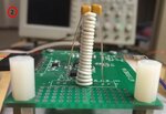
360反馈意见截图1732120595100116.jpg

I think the drift issue is solved.

Right now one of the problems is on weekend the result is strange, but it's not drift.

The other is the three channels are probably coupled and not independent as I said in the other post which I hope maybe you can give me some suggestions.

Thanks.

- - - Updated - - -

Record room temperature and humidity.


Thanks for your reply. I will do it after I get the necessary instrument.
 

Status
Not open for further replies.

Part and Inventory Search

Welcome to EDABoard.com

Sponsor

Back
Top