Continue to Site

Welcome to EDAboard.com

Welcome to our site! EDAboard.com is an international Electronics Discussion Forum focused on EDA software, circuits, schematics, books, theory, papers, asic, pld, 8051, DSP, Network, RF, Analog Design, PCB, Service Manuals... and a whole lot more! To participate you need to register. Registration is free. Click here to register now.

[SOLVED] Advice on my first SMPS device.

Status
Not open for further replies.

David_

Advanced Member level 2
Joined
Dec 6, 2013
Messages
573
Helped
8
Reputation
16
Reaction score
8
Trophy points
1,308
Location
Sweden
Activity points
12,220
Hello.

I am trying to design my own SMPS supply and I could really need some help.

The SMPS will be used in a lab power supply with a linear post-regulator, so I am searching for a adjustable SMPS, I am reading about all different topologies but I can't make sense of which I should go with. Buck I guess but I'm not sure.

Also, I have searched for adjustable switching voltage regulators but they all need a "lower than line voltage" as input. So I still need my big line-transformer.
How would I go about designing a SMPS that uses rectified line-voltage?
I understand that such a topology would not be contained in a IC but does these topologies have a name that I can research?

Whatever I'll go for will need to be isolated.

Regards
 

Why don't yu try a Linear Adjustable Regulator just after this SMPS ?? You may design your SMPS ( for instance 85-270VAC )then you can connect a variable regulator then..
SMPSs work still rectified line voltage so DC.Flyback is a good choice..
 

Yes, using a post-regulating linear regulator...(if it is called that?) is the idea.
I've found LT3500:
http://cds.linear.com/docs/en/datasheet/3500fc.pdf

which is a switching regulator with a linear regulator in the same IC, the output current is almost to low, as it will be a lab power supply there really aren't a "to low current" but 2A is at the lower limit of what I want.

This is a project already designed but using only a linear regulator and the power dissipation is really un-acceptable, but I think I will use the transformer intended for that supply.
Its a 2x28Vac, 1x12Vac 300VA toroidal 230Vrms 50Hz transformer, if I do use that I can get one of those practical regulators from Linear Tech. I think that building a line driven switching supply is way over my head and I should start with something simpler.
Usually I prioritize learning for all my projects but here I actually just want to finish my lab power supply with the specifications as I have set them, I do have a need for it.
The supply will have two identical channels that can be connected freely as the are floating.

LT8614 is a 42V, 4A Synchronous, Step-Down Silent Switcher, with 2.5μA Quiescent Current.
And it has a ripple voltage below 10mV at all loads, and that is then regulated by a TPS7A4701 36-V, 1-A, 4.17-μVRMS, RF LDO Voltage Regulator.
If I can increase the output current, of course I can but I'm not sure about the following:

I have a linear regulator who's output goes to the base of a NPN darlington transistor whose collector is connected to the same supply as the regulator, if the rail before the circuit has 10mV ripple, how much of that ripple will be present at the NPN darlington emitter?
Is it all or does the regulator provide some improvements?
 

"Usually I prioritize learning for all my projects but here I actually just want to finish my lab power supply with the specifications as I have set them, I do have a need for it.".

You know, that is a VERY WISE decision.
I see too many people in this forum attempting to run before they learn to walk.
The approach you are taking, designing and building a straightforward circuit before you attempt a major challenge like an off-line power supply, is correct.
 
  • Like
Reactions: David_

    David_

    Points: 2
    Helpful Answer Positive Rating
Thanks for the encouragement, I do feel more sure about my direction.
I will go through my thoughts about the circuit and everything, I am sure to make some mistakes and faulty assumptions on the way.

I found this:
http://e2e.ti.com/support/power_man...-measuring-and-reducing-output-voltage-ripple
which is a guide on how to measure power supply ripple and noise specs and where these comes from and how to combat them in a switching regulator circuit, a buck-converter as the example, from this I've found out that what I will have to combat is at one hand low frequency ripple voltage and on the other hand high frequency noise.

The low frequency ripple voltage is caused by the inductors ripple current and the output capacitor’s impedance at the switching frequency of the regulator. Depending on what the capacitors impedance consists of the ripple will take different shapes, a ESR dominated impedance will produce a triangle shaped ripple while if there are ESL there will be voltage steps at the peak and valleys of the ripple waveform, and if both ESR and ESL are small as with a ceramic capacitor the ripple will be sinusoidal.
There are then two ways of reducing the LF ripple voltage:

Reduce the inductor ripple current, ether by increasing the switching frequency or by increasing the inductors inductance.
Or use output capacitor(s) with lower impedance at the switching frequency.

The high frequency noise which shows up as voltage spikes is caused by the parasitic capacitance of the output inductor. There are fast edge waveforms at the switching node that couples through this parasitic capacitance, so the greater the capacitance of the inductor the greater the high frequency voltage spikes(or noise).

To reduce them one will need to pay attention to the board layout, that's it... More info in the link.

Okey, so how does this impact my choices...
When looking for a regulator I search Digikey, by the way, does any one have any other prefered site for parametric searching of components?

Any way, I see a lot of regulators with a frequency of 200kHz and then others with 200kHz-2(or 3)MHz. From what I have read it seems that I would like to use one of those with adjustable frequency and set it as high as possible. But is there any other factors I'm not aware of that a high switching frequency would impact?

And then I would like to use a as high as possible value inductor, what is it that determines the maximum inductance that can be used?

I haven't really read any datasheet for any regulators jet but I shall choose one tonight and go through it, I'm hopping to find some good info in there.

Then about the inductor capacitance... Shouldn't there be any technique to reduce it? And I don't mean any that would be applicable in a professional production situation but when making my own hobby coil should I not be able to reduce it somehow?
Some extra/special insulation maybe, some special winding technique?

This project does not jet have a chassi so space is not a constraint, I would be more happy to use a bigger inductor than to accept more ripple. I will have to read up on winding inductors and I guess I will use a toroidal core, but first I have to choose the switching frequency so a suitable material can be selected.

That's where I'm at right now, I'm sure some of my questions will answer them self's when I read some datasheets.
 

But is there any other factors I'm not aware of that a high switching frequency would impact?

And then I would like to use a as high as possible value inductor, what is it that determines the maximum inductance that can be used?

Suppose you wind an inductor which you plan to make 100 uH (a typical value). In reality it might turn out a bit high, or a bit low. Not a problem. You'll simply adjust the frequency and duty cycle, so that your converter gives you proper performance. There is a wide range of frequencies that will do this.

It is important that your wire be thick enough to handle your desired Amperes. Also that the core have sufficient metal so it does not saturate when the waveform reaches 1.5 to 2x your target Ampere output.

The higher the inductance, the lower the frequency range. It is common to shoot for 20 kHz, because the human ear cannot hear such high pitches.

I have tutorial simulations which are animated and interactive. They are in post in the thread linked below. You can click my links to load the Java applet, load my schematic, and run it on your computer. Falstad's simulator is very capable that way.

https://www.edaboard.com/threads/268178/
 
  • Like
Reactions: David_

    David_

    Points: 2
    Helpful Answer Positive Rating
When you say that it is common to shoot for 20 kHz, isn't 20kHz a very low frequency?
Or does it refer to the frequency of the switching?

Unfortunately I can't get Java to run with firefox, I find that Java can only run in windows 8.1 desktop mode... But I will get another browser cous those simulations looks very interesting and looking through the list there are a few topics I sure could benefit from taking a look at again.
 

When you say that it is common to shoot for 20 kHz, isn't 20kHz a very low frequency?
Or does it refer to the frequency of the switching?

20 kHz is a frequency which is manageable and convenient to work with. Its pitch is higher than human hearing, yet it is a low enough frequency for ordinary components to operate.

You can go for a faster frequency if you wish (in the hundreds of kHz). The inductor can be a smaller Henry value. However at some point you are liable to need devices which are made to operate at high frequencies.

There are commercial IC's which are made to control a SMPS. Some of them operate in the hundreds of kHz.
 
  • Like
Reactions: David_

    David_

    Points: 2
    Helpful Answer Positive Rating
Is it possible to say(in general) something about the noise at the output of the converter and its operating frequency?
Or can a converter running at 20kHz be comparable to a converter running at 1MHz?
I guess that it will depend on lots of other things but see the question as a very lose and hypothetical comparison.
I am trying to imagine what component effects the frequency might cause, effects that impact the converters output noise and stability. Lots of the ICs I have looked at goes from 200kHz to 2-3MHz, but I will keep 20kHz in mind and try to do some research about how the frequency chosen will impact the circuits needs.
 

As a rule of thumb, the higher the switching frequency, the more critical the board layout becomes, and the most effect the parasitic elements impair on the noise performance of a converter.

20 Khz is a relatively "easy" frequency to work with.
As I advised in my previous post, start with something simple, make it work, learn from it.
Then move the next step in the ladder.
 
  • Like
Reactions: David_

    David_

    Points: 2
    Helpful Answer Positive Rating
Hello again, some time has passed and I am about to settle on a specific regulator design.

But when I read datasheets for these switching buck regulators something keeps bother me, LM22678 is a buck regulator which can output 1,2V - 37V(4-42V input).
But it is really only meant for up to 5V and this seems to be the case very often, or perhaps more accurately it is optimized for up to 5V. I really do want one of these with internal loop compensation so as to make for a easy board layout but I don't understand what it would mean to use one of those for a output of up to 30V...

Also, the main inductors value is among other things a function of the output voltage.
It seems more and more as these regulators are not suited for 0-30V adjustments, what do you think?
I can't say what the effects would be but it seems clear that many things would differ in the voltage output when setting it to 3.3V and 28V.

There are so many regulators to choose from so I have found the right one for me I think but actually lost track of which it was and now I can't find it:)

Texas Instruments have this nice "Simple Switcher" initiative which is suppose to more or less give you complete designs but they are all adjustable up to 5V...

I can't really say what will be the main use in regard to voltage range for my power supply but I am waiting on parts to finish the linear regulator which will do the post-regulation after the switcher in this thread.
 

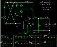
In case you are reluctant to go ahead with a commercial IC, here is a buck converter driven by a single op amp, and a couple of transistors.


It is adjustable. Apply your desired reference voltage at the non-inverting input.

It is powered by mains AC, rectified and filtered. However this means it is not isolated.

The power supply to the op amp is 'understood'. It is not shown. It can be low voltage.

The two ground icons are connected.

It's okay to use a smaller inductor, at a faster frequency.
 
  • Like
Reactions: David_

    David_

    Points: 2
    Helpful Answer Positive Rating
I found the kind of IC that appears really attractive, such as LTC3115:
https://www.linear.com/product/LTC3115-1
However I like your suggestion and I will look into it but not for this project, I need two identical floating channels so they can be combined to produce +-10V as a example.
But I really like when doing it on your own can be a viable option, when looking at linear regulators I sometime want to do my own but it ends up with the insight that a regulator IC gives lots of features that I simply can't match or that the circuit would take to much of my time. But learning is always(almost) the point and such a circuit would be invaluable in that regard.

Back to the switcher, the one I'm going for(LTC3115) can operate from 100kHz to 2MHz and I intend to use it at 100kHz. I don't mind larger inductor and capacitors if the end result is lower noise and I have found out that high frequency switchers is I think to hard layout-wise for me to implement successfully, I have done a few of my own PCB layouts but they has not jet given me any insight in what is and is not a good idea.

This is a quote from the datasheet of LTC3115:
" In noise sensitive applications, the converter can also be synchronized to an external clock via the PWM/SYNC pin."

But how does that enable you to combat noise? From other reading I have done its clear that synchronization to an external clock is one part of some system technique to avoid problems with noise but how I have no idea.

Also, can I make the inductor to big?
I mean at some point I can think that some aspect of how the inductor is meant to function will degrade or something, I'm just guessing here but documents tell me that a larger inductance result in higher current capability and lower current ripple but that it also means higher cost larger physical size and that is the limitation.
But I am not making a commercial product and I am prepared to sacrifice significantly more board space than in a professional environment if the sacrifice reward it self as lower noise/ripple.
This is a pre-regulator for a lab power supply and I have invested a great deal of time and energy and will continue to do so in order to be able to really be satisfied with the end capabilities, if I try to think like a engineer and try to adapt the right mind set then this is not a good idea but the quality of the output voltage is the only important aspect of this project.

I can't find the right English word but this feels kind of immature but I know what I want in this case and I am going to stick with this IC and as suggested get it working and then move on.

I will use the regulator in constant PWM so know I just have to get through the datasheet and get a grip of capacitors and inductors. And look into adding a second LC filter perhaps.
 

To close this thread as solved I'd thought that I should tell what I ended up doing.
I looked at a lot of ICs and in the end I choose LTC3864 60Vin low Q step-down dc/dc controller and with that a P-channel MOSFET, the design is not jet finished but this IC gives me control over frequency and what mode of operation is being used as well as setting the current limit, setting loop compensation, Power good range and UVLO if needed. I found some regulators from TI that had the current I was looking for with internal switches but non of those let me control mode of operation and as this is for a lab power supply I did not want those eco modes that kicks in at low currents. anyway here is a schematic and thank you all for your posts.
bbuck.png

Regards
 

Status
Not open for further replies.

Similar threads

Part and Inventory Search

Welcome to EDABoard.com

Sponsor

Back
Top