Continue to Site

Welcome to EDAboard.com

Welcome to our site! EDAboard.com is an international Electronics Discussion Forum focused on EDA software, circuits, schematics, books, theory, papers, asic, pld, 8051, DSP, Network, RF, Analog Design, PCB, Service Manuals... and a whole lot more! To participate you need to register. Registration is free. Click here to register now.

shunt 24V rail to reference voltage using opamp?

Status
Not open for further replies.

harvie

Full Member level 1
Full Member level 1
Joined
Sep 10, 2014
Messages
98
Helped
2
Reputation
4
Reaction score
2
Trophy points
1,288
Location
Prague
Activity points
2,486
Hello,
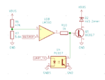
i have following circuit:

bustx.png


"VBUS" is 24V bus limited to 200mA, it serves for both power and data transfer.
If i want to transmit logic HIGH i leave it like that. If i want to transmit logic LOW i pull it down to 7V.
That way i can always have regulated 5V supply using LDO.

Problem is that i want to support multiple standarts, each of them uses different threshold voltages.

So i am using isolated ADC (PWM with optocoupler and RC low pass filter) to provide reference voltage "BUSREF" which is used as threshold for opamp. I am succesfully using this to RX the bus and provide TTL output using optocoupler. But now i want to TX so i need to pull down the bus to reference voltage when triggered using optocoupler.

There is also a zener diode that prevents bus from going lower than 5V if there's something wrong with reference voltage.

The attached TX circuit "kinda works", but it ends up doing lot of weird stuff and voltage transitions on bus are slow and ugly. I am unable to run UART serial data through it. Even baudrate of 2400 does not work properly. So i need to get sharp and clean transition. Any ideas how to improve?


I've tried following without success:

- using darlington transistor
- adding hysteresis resistor to opamp
- moving optocoupler from base of the transistor to positive input of the opamp

- - - Updated - - -

BTW i use LM385 opamp, i ditched LM393 comparator that i've originaly designed to circuit, because it can only sink small current, while LM385 can both sink and source bit more current
 

I fail to see how this circuit could work at all.
Both the comparator and the optocoupler are open collector, and without a pull up resistor, the output will always be zero.
 

I fail to see how this circuit could work at all.
Both the comparator and the optocoupler are open collector, and without a pull up resistor, the output will always be zero.

Thanks for reply. I've mentioned that i use LM358 opamp instead of LM393 for this very reason... This was the first problem i've encountered. Didn't updated the schematic yet..
 

Hi,

I see no reason why pulling 24V down to 7V.
This causes a lot of power dissipation and EMI.

9V or even 12V would be an improvement.

But you are not the first to build a data communication via a DC supply line.
Did you read through descriptions? If not, do so.

Instead of pulling down voltage I'd rather just draw current.
And I'd not use absolute levels, but relative levels...this enables other DC loads to be connected on the bus.
And to keep power dissipation low while improving SNR I'd use shorter pulses. Like IrDA does. Maybe you can even use IrDA chips.

Klaus
 

Hi,
I see no reason why pulling 24V down to 7V.

I did not invented this communication protocol. I just need to interface with it. This is very common for heating boiler control. But there are several variants with different voltage levels and i need to create single frontend with variable thresholds. I guess that the trick is the bus master provides low current 24V supply on top of high current 7V supply or something like that. So it's easy to pull to 7V without drawing much current. But that's kinda out of the scope of my question...
 
Last edited:

There's a lot of similar "single wire" communication protocols in use, no doubt that it can work in principle. The circuit in post #1 however makes no sense. Why are you feeding back the output of the receiver circuit to the transmitter with inverted polarity?

I would expect separate RX and TX circuits, connected to VBUS and the respective UART lines. If you want isolation, separate opto couplers for RX and TX are required.

Your report of measurement results is rather vague. If you want actual help, show oscilloscope measurements along with the final circuit setup (correct components values).
 

Why are you feeding back the output of the receiver circuit to the transmitter with inverted polarity?

I would expect separate RX and TX circuits, connected to VBUS and the respective UART lines. If you want isolation, separate opto couplers for RX and TX are required.

https://en.wikipedia.org/wiki/EBUS_(serial_buses)#Physical_layer

This is TX circuit. RX circuit is however quite similar, it also has voltage divider and opamp with optocoupler anode at its output.
Reason why i use the TX opamp is so i can use various voltage references. If the bus voltage is higher than threshold it should be pulled down. Basicaly the same circuit as internals of TL431 except for higher current sinking capability and reference voltage that can be set using DAC. Also it can be disabled by optocoupler to send the data.

I am not at the lab right now, but the scope measurements of bus voltage were showing weird stuff. sometimes the transition was sloping up and down rather than sharp taking sharp steps, sometimes it was combination of both. Also it was relatively random, sometimes there is sharp transition, sometimes combination of sharp and slope, it didn't really showed any obvious regular patterns. Overall the bus voltage looked like himalayas with occasional pieces of squares of various amplitude. (sorry for this lame description, i might be able to get some real images next week)
 
Last edited:

An apparent problem is that the negative feedback loop has no compensation for the added loop gain from the transistor.
That can lead to an unstable output.

How is the 200mA bus current limit done?
Is it just a resistor, or some form of active limit?
That can also affect the stability.

We need the complete circuit to make an informed answer to your problem.
 

Status
Not open for further replies.

Similar threads

Part and Inventory Search

Welcome to EDABoard.com

Sponsor

Back
Top