MARGD
Newbie level 4
All,
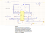
I'm currently working on a design that's trying to use the LTC4020 battery charger, and I'm at a loss to understand what I'm doing wrong. Here's my schematic.

When I apply 48V to Vin, I get between 24V and 38V on Vout, and nothing on the battery terminal (with no battery connected) and it's very unstable.
When I probe at the gates for the four FETS, here's what I see:


Which is clearly wrong. At first I thought it was because I mistakenly set my Vfloat to 57V, so I corrected that (Vfloat was reduced to 54V and Vmax was set to 55V) but the problem remained. It's not a damage issue: First, Linear's application engineer assured me that there would be no damage to the part unless my input exceeded 60V, which it did not and second I tested the updated values on an untouched board and it still didn't work.
If I apply 46V instead of 48V to the updated 54/55 circuit I get results that are closer to what I expect (52V out on an open circuit), but still unstable and the gate control lines do the same as the above screenshots.
I've been in touch with Linear Tech support and they recommended changing the circuit to decrease my Vshutdown threshold (set for 32V by changing R5 to 385kohms) and change my switching frequency (R8 = 47.5kOhm) and reduce my charge current to 400mA by changing R11 to 125mOhms.
I still don't get the correct output. I tried connecting to my battery, which was discharged to an open circuit voltage of 52V. When I connected that to my circuit, and then applied 48V (current limited to 700mA) to VIN, the circuit popped and my sense resistor was blown open like a fuse.
I'm currently waiting for replacement sense resistors to see if I damaged the LTC4020, which I expect is the case.
The thing I don't get is: Why isn't the circuit performing? I followed the datasheet for all calculations. Linear's tech support found no significant differences between my schematic and the application examples (in fact I mostly just copied the typical design example from page 38 of the datasheet, subbing component values based on the application section guide) The layout has one needed correction that I noticed after it was already fabbed (my high-side gate lines cross a split in a plane but I'd expect that to give me efficiency reductions, not catastrophic faults.)
I've designed synchronous buck converters before, and never had a problem like this. Clearly I'm missing something, but I have no idea what.
I'm currently working on a design that's trying to use the LTC4020 battery charger, and I'm at a loss to understand what I'm doing wrong. Here's my schematic.
When I apply 48V to Vin, I get between 24V and 38V on Vout, and nothing on the battery terminal (with no battery connected) and it's very unstable.
When I probe at the gates for the four FETS, here's what I see:
Which is clearly wrong. At first I thought it was because I mistakenly set my Vfloat to 57V, so I corrected that (Vfloat was reduced to 54V and Vmax was set to 55V) but the problem remained. It's not a damage issue: First, Linear's application engineer assured me that there would be no damage to the part unless my input exceeded 60V, which it did not and second I tested the updated values on an untouched board and it still didn't work.
If I apply 46V instead of 48V to the updated 54/55 circuit I get results that are closer to what I expect (52V out on an open circuit), but still unstable and the gate control lines do the same as the above screenshots.
I've been in touch with Linear Tech support and they recommended changing the circuit to decrease my Vshutdown threshold (set for 32V by changing R5 to 385kohms) and change my switching frequency (R8 = 47.5kOhm) and reduce my charge current to 400mA by changing R11 to 125mOhms.
I still don't get the correct output. I tried connecting to my battery, which was discharged to an open circuit voltage of 52V. When I connected that to my circuit, and then applied 48V (current limited to 700mA) to VIN, the circuit popped and my sense resistor was blown open like a fuse.
I'm currently waiting for replacement sense resistors to see if I damaged the LTC4020, which I expect is the case.
The thing I don't get is: Why isn't the circuit performing? I followed the datasheet for all calculations. Linear's tech support found no significant differences between my schematic and the application examples (in fact I mostly just copied the typical design example from page 38 of the datasheet, subbing component values based on the application section guide) The layout has one needed correction that I noticed after it was already fabbed (my high-side gate lines cross a split in a plane but I'd expect that to give me efficiency reductions, not catastrophic faults.)
I've designed synchronous buck converters before, and never had a problem like this. Clearly I'm missing something, but I have no idea what.