dicket
Junior Member level 2
It seems that Load Pull is one of the most useful conception in the RF Power Amplifier.I am confused with Load Pull for a long time.What's it?Anybody who can give me some explanation?Thanks!
Follow along with the video below to see how to install our site as a web app on your home screen.
Note: This feature may not be available in some browsers.
dicket said:It seems that Load Pull is one of the most useful conception in the RF Power Amplifier.I am confused with Load Pull for a long time.What's it?Anybody who can give me some explanation?Thanks!
dicket said:It seems that Load Pull is one of the most useful conception in the RF Power Amplifier.I am confused with Load Pull for a long time.What's it?Anybody who can give me some explanation?Thanks!
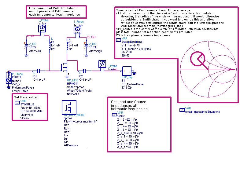
To avoid this situation load pull simulation with a variable impedance, measures the output power level for each of the impedance value and then decides at which load value for a given input power level, the device gets the maximum value.
How to determinate the field within which we can change the impedance,for example,how to choose the value of s11_rho and s11_center in the following image?
How to determinate the field within which we can change the impedance,for example,how to choose the value of s11_rho and s11_center in the following image?
huvarda said:I will use FLC167WF. Can't we use the s-parameters given in the datasheet for matching. If we can't what is the purpose of publishing these parameters?
If I can't use these parameters how can I use the loadpull technique for output matching?