polarized
Member level 4
pt2262 schematic
Hello,
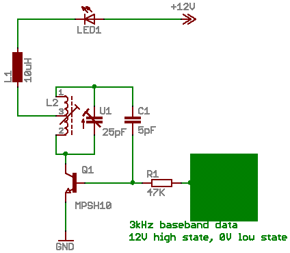
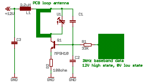
I am trying to understand the electrical schematics I have attached into this topic. The first schematic is showing the recommended circuit by the producer of the encoder chip PT2262, which is mainly used for radio remote control etc... The other schematic is using the same encoder chip, but the RF part is a little bit different. The second schematic is from a real device that I opened and made the diagram. The whole point is that I would like to increase the distance of this system. At the moment its using a PCB loop antenna and I would like to add an whip antenna in a telescopic form. I have measured the baseband signal with the scope and its a simple 3kHz digital waveform where the high state is 12V and the low state is 0V. For example at the moment i think this is a kind of a ASK system where as long the baseband signal is high the 433.92MHz is running and as soon its low the oscilator is stopped and so on... I dont have the values of all of the components in the second schematic as the elements are SMD without markings. Could I influence on the radiated power by changing some element values? I have also calculated in the second diagram the base current and the collector current, for example collector current is 18mA, this is a static bias value. The hFE of this transistor which I think is the same as its in the first diagram the MPSH10 is around 60. Could someone please describe the way how do the circuits attached operate for example the following things:
1.are they using common base or common emiter mode if the transistors at all are working as small signal RF transistors?
2. what kind of an oscilator circuit are we talking about in both of the circuits?
3. What about the first circuit, the encoder company didn't give any information about the center tapped inductance, where is the antenna in this case?
4. can I use a simple whip antenna instead of the loop antenna, do I need any impedance matching?
5. would the range be greater if a whip monopol antenna is used and which circuit is better and easier to modify for increasing the range?
6. even 100 meters larger range would be very good for me.
7. any deeper info how are the circuits operating.
8. Is there another way to increase the range of these circuits, maybe adding an additional RF transistor for more gain?
Thanks for your help.


Added after 2 minutes:

Hello,
I am trying to understand the electrical schematics I have attached into this topic. The first schematic is showing the recommended circuit by the producer of the encoder chip PT2262, which is mainly used for radio remote control etc... The other schematic is using the same encoder chip, but the RF part is a little bit different. The second schematic is from a real device that I opened and made the diagram. The whole point is that I would like to increase the distance of this system. At the moment its using a PCB loop antenna and I would like to add an whip antenna in a telescopic form. I have measured the baseband signal with the scope and its a simple 3kHz digital waveform where the high state is 12V and the low state is 0V. For example at the moment i think this is a kind of a ASK system where as long the baseband signal is high the 433.92MHz is running and as soon its low the oscilator is stopped and so on... I dont have the values of all of the components in the second schematic as the elements are SMD without markings. Could I influence on the radiated power by changing some element values? I have also calculated in the second diagram the base current and the collector current, for example collector current is 18mA, this is a static bias value. The hFE of this transistor which I think is the same as its in the first diagram the MPSH10 is around 60. Could someone please describe the way how do the circuits attached operate for example the following things:
1.are they using common base or common emiter mode if the transistors at all are working as small signal RF transistors?
2. what kind of an oscilator circuit are we talking about in both of the circuits?
3. What about the first circuit, the encoder company didn't give any information about the center tapped inductance, where is the antenna in this case?
4. can I use a simple whip antenna instead of the loop antenna, do I need any impedance matching?
5. would the range be greater if a whip monopol antenna is used and which circuit is better and easier to modify for increasing the range?
6. even 100 meters larger range would be very good for me.
7. any deeper info how are the circuits operating.
8. Is there another way to increase the range of these circuits, maybe adding an additional RF transistor for more gain?
Thanks for your help.


Added after 2 minutes:
