qureshi
Banned
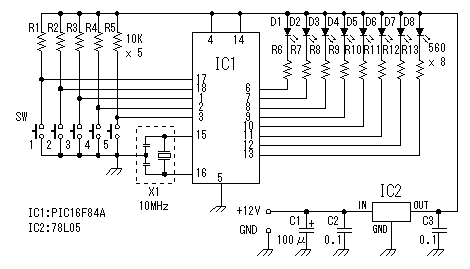
I made LED flash circuit which is often used as the PIC software making practice.
This circuit controls the blink of eight LEDs with the software of PIC.
The blinking pattern can be changed with five switches.
Parts List:
PIC: PIC16F84A
Processor Frequency: 10MHz
LED: High brightness LED x 8
Blink pattern: Five kinds

Circuit Explanation:
Five pins from RA0 to RA4 are used as the input pin.
These pins are pull-uped with 10K ohm resisters. So, when a switch isn't pushed, the input becomes H level ( +5V ). and when a switch is pushed, it will become L level ( 0V ). When the switch closes, the chattering occurs. The chattering is the phenomenon which occurs with the bound of the point of contact. The opening and shutting of a point of contact is repeated in short time..
I don't put the prevention circuit of the chattering at the circuit this time. When the software detects that the switch is closed once, the blink processing of LEDs are executed in the time which is longer than the chattering.
Here is the Source Code and hex file:
Thanks to all.
This circuit controls the blink of eight LEDs with the software of PIC.
The blinking pattern can be changed with five switches.
Parts List:
PIC: PIC16F84A
Processor Frequency: 10MHz
LED: High brightness LED x 8
Blink pattern: Five kinds

Circuit Explanation:
Five pins from RA0 to RA4 are used as the input pin.
These pins are pull-uped with 10K ohm resisters. So, when a switch isn't pushed, the input becomes H level ( +5V ). and when a switch is pushed, it will become L level ( 0V ). When the switch closes, the chattering occurs. The chattering is the phenomenon which occurs with the bound of the point of contact. The opening and shutting of a point of contact is repeated in short time..
I don't put the prevention circuit of the chattering at the circuit this time. When the software detects that the switch is closed once, the blink processing of LEDs are executed in the time which is longer than the chattering.
Here is the Source Code and hex file:
Thanks to all.
Last edited by a moderator: