Continue to Site

Welcome to EDAboard.com

Welcome to our site! EDAboard.com is an international Electronics Discussion Forum focused on EDA software, circuits, schematics, books, theory, papers, asic, pld, 8051, DSP, Network, RF, Analog Design, PCB, Service Manuals... and a whole lot more! To participate you need to register. Registration is free. Click here to register now.

Why output voltage stops changing at a low value in op-amp output stage?

Status
Not open for further replies.

fanrong

Banned
Joined
Oct 20, 2006
Messages
122
Helped
3
Reputation
6
Reaction score
1
Trophy points
1,298
Activity points
0
Hi everyone :

I make a simulation on the circuit in the figure . I found when the
load resistor value is low , the output voltage will stop changing at
a low value in spite of the change of input voltage .
For example , when do a dc sweep for V2 from 0 - 3V , if Rl is 200 , the output voltage will stop increase at 0.5V . But if Rl is 2k , the output voltage can
be 2V .
Anyone can explain it ?
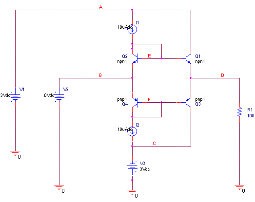
70_1165983962.GIF
 

Re: opAmp output stage

it is only V=IR relationship. let say your current is constant, the higher your resistance higher voltage will drop across the resistor.
 

Re: opAmp output stage

your output load is very small. Assume R1 is close to zero, then the output voltage will hold close to zero too.
 

Re: opAmp output stage

what is the function of this circuit.
 

Re: opAmp output stage

fanrong said:
when do a dc sweep for V2 from 0 - 3V , if Rl is 200 , the output voltage will stop increase at 0.5V . But if Rl is 2k , the output voltage can
be 2V .

well, that is a bit strange.
1. you could observe the triodes' states while sweeping v2. are they in amplifing region all the time?
2. maybe 10uA is too small. if R_out is 200ohm, and you want a +2V output, then for the npn-output-triode, I_ce = 10mA. assume beta = 100, then I_b = 100uA. Oh..... your bias circuit cannot work properly in that case.
 

Re: opAmp output stage

Hi
In fact, since your miximum positive output current can be 10u*B1, this value for large input voltage is limited by transistor saturation and positive supply voltage, but since your B1 is probably low for full range of input the total output current is 0.5/100=5mA this means B1 is about 5mA/0.01=500.
therefore, since I1 is very small your maximum output current is limited to 5mA (for full input) your maximum output voltage is 0.1K*5mA=0.5V
If my reply was useful, it's not bad to help!
BTW, you can see more about these in Power amplifiers chapters of microelectronics books.
If it has helped you, then if you want press the Helped me button; it doesn't cost you any points!
Good luck!

Regards,
SAZ
 

Status
Not open for further replies.

Part and Inventory Search

Welcome to EDABoard.com

Sponsor

Back
Top