Continue to Site

Welcome to EDAboard.com

Welcome to our site! EDAboard.com is an international Electronics Discussion Forum focused on EDA software, circuits, schematics, books, theory, papers, asic, pld, 8051, DSP, Network, RF, Analog Design, PCB, Service Manuals... and a whole lot more! To participate you need to register. Registration is free. Click here to register now.

Shielding for voltage measurement of a 100 M Ohm

Status
Not open for further replies.

fala

Full Member level 5
Joined
Sep 18, 2005
Messages
249
Helped
19
Reputation
38
Reaction score
4
Trophy points
1,298
Activity points
3,569
high impedance voltage measurement

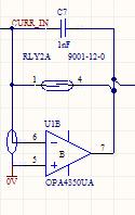
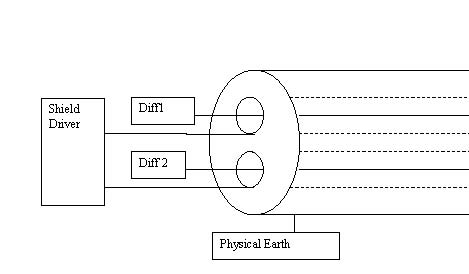
Hello, I want to measure a very small current at nA Scale precisely over a 100 M Ohm Resistor and read the value by a 16 bit ADC, I know there are many factors that can influence success of such measurement but I want to focus on shielding from outside noise in this post. I have two options, May someone tells me what option is better and why?
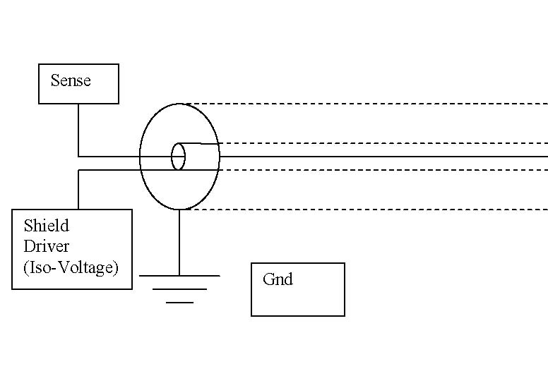
1- shield using physical earth and then connecting physical earth to system ground by a high impedance connection.
2-shielding by physical earth and connecting physical earth directly to system ground at one point(power supply)
 

ina116 adc

As far as shielding and grounding is concerned there is no "The Absolute, Best Right Way to Do It" ..

Both options of your's are just different "schools of thoughts" ..

If I were you I would first try the star configuration (option 2), but you will have to experiment a little bit ..

Regards,
IanP

"Grounding and Shielding Considerations for Thermocouples, Strain Gages, and Low-Level Circuits"
http://www.iotech.com/catalog/techtip/TechTip_60201.pdf
 

    fala

    Points: 2
    Helpful Answer Positive Rating
shielding for low noise measurement

With nA measurement you have to prevent leakage between signal wire and shield and only way to do that is to drive shield with same or very close potential to the signal wire. Specialised IC's like INA116 already have shield drivers built in them. For differential input that would mean using two coaxial connectors. All wiring in this case have to be symetrical and only overal shield should be done with example above. To connect your meter to measurement source you could use VGA cable assembly that has 3-4 coaxial cables in it with overall shield as well. This cable should have ferrite installed on it, same way PC monitor VGA cable has.
Another very important issue is powering of your meter. If your signal source is not very well isolated, you have to isolate meter circuit very well to avoid creating pickup loop through ground. This can be achieved either by using batteries (which are excellent low noise source) or have very high isolation power supply.
At last but not least, 100M resistance will have quite a bit of noise, so using integrator method instead of this resistor is probably the best to narrow down bandwith.
Your ADC likely does not have leakage specs good enough to perform such measurement directly as you intended.
 

    fala

    Points: 2
    Helpful Answer Positive Rating
Hello, Thanks IanP and Sinisa. The link was very useful and the concept of developing common mode voltage due to capacitance of shield was completely new to me, thanks a lot. I have two more questions:
1-Regarding the transformer, unfortunately I can’t use battery as suggested by Sinisa so I have to live with transformer. Should I put the transformer in a separate metal enclosure and connect the enclosure to middle tap of transformer?
2-Regarding the sensor lead that goes outside the metal enclosure, Sinisa did you mean something like this?
34_1165111698.jpg

From VGA did you mean computer monitor cable, Is it twisted pair at center as well as 3-4 Coaxial?

Thanks
 

1. Putting transformer in a separate metal enclosure is a very good idea ..
Another thing worth cosidering is the use of two separate voltage regulator blocks - one for analog section and the other for digital section ..

2. I am not sure how have you designed the input stage, but in biomedical instrumentation amplifiers there is only one shield on cables and this shield is driven by one common shield driver, sa shown on the attached picture ..
There is no other shield on top of that and it is common practice to use high quality shielded cables with shielding coverage >95% ..

Regards,
IanP
 

    fala

    Points: 2
    Helpful Answer Positive Rating
Shields should be driven as Ian has shown on schematics. In addition, there should be overal shield that is connected to instrument enclosure and grounded at your signal source. This ground connection should be made only on ONE spot. On top of overall shield, usage of ferrite on the cable is recomended. Instrumentation that deals with small currents ususally makes use of triaxial cables. Your instrument should be floating so there is no pickup loop created through your power supply and that is where high isolation power supply steps in. There are DC-DC converters that are designed for this purpose, I could look up what I have used in some simmilar projects.
 

    fala

    Points: 2
    Helpful Answer Positive Rating
Thanks a lot IanP and Sinisa. Regarding the output cable, I saw the scheme that has been posted by Ian in some application notes but I have some concerns.
1- It has been said many times by many application notes and indeed in the application note that has been posted kindly by Ian that such cables should be twisted pairs because of uneven mutual inductance in each lead, so I think the scheme that has been posted by Ian should eventually twist around each other, am I right?
2- In the scheme that has been posted by Ian Impedance of guard to physical earth is about 10K ohm, though impedance of sense line is even higher in matter of billion or trillion ohms because of high input impedance of Opamp butl wouldn't it be a good practice if the entire assembly (twisted pair, each guarded) be protected by another layer of shield with zero impedance to physical earth, or it is just waste of time and money and I should pay attention to other factors?
3- Can I use ordinary monitor cable for this purpose?
 

Symbol for ground in Ian's schematics does not denote physical ground, but 0V potential of your floating power supply. Physical ground is not shown on that schematic.
Twisted pair is more resistant to interference as it has more symetrical coupling to its surroundings than just to wires besides each other. You can't realy twist coaxial cables in same way. You could use coxial cable for monitor if it has couple of coaxial cables in it and overall shield.
If you expect current leakage between your source and earth, you could drive it as well same way you drive coax shields, but with separate opamp.
Pay attention that all your connections are symetrical and complementing connections are on same temperature to avoid Tc problems. Route differential wires and routes close to each other with shield route between and arround them. And keep them short as possible. Use instrumentation amp instead of discrete solution as shown in Ian's schematic, it would have much better common mode rejection.
C&D Technologies makes HB04U series power supplies with high isolation that would be good for you r your purpose.

Here is example of one of my projects with high impedance input:
50_1165249244.GIF
 

    fala

    Points: 2
    Helpful Answer Positive Rating
Thank you Sinisa
I understand that what has been shown in Ian’s schematic is signal ground but I presumed (maybe wrongly) that in this schematic physical earth has been connected directly to signal ground.
Anyway, First what I want:
1-I want low leakage of source so we concluded that I have to guard the source but since the source is isolated from physical earth I do not expect leakage to physical earth.
2-I want low interference from environment so I think I have to shield the sense wires with physical earth and preferably if I can, I should use twisted pair for transferring the signal.

I think I'm a bit confused by this part of your reply,
If you expect current leakage between your source and earth, you could drive it as well same way you drive coax shields, but with separate opamp.
what you mean from separate OpAmp
You mean this ?
57_1165253274.jpg

The scheme above is similar to what I have used in a project earlier.
What is the importance of 2GOhm bias resistors in input of your schematic, what happens if someone removes them?
Do I have to forget twisted pair and look for something like this?
5_1165252504.jpg

Sorry, It seems that I asked too many questions, I hope it has not bothered you.
Thanks.[/quote]
 

Well... Main idea behind driving shield is to have low impedance shield arround sensitive high impedance wire with same potential as that wire. Having low voltage means that leakage current I=U/R will be low as well, even if insulation beween two isn't perfect. If you are measuring 1nA with 1% accuracy it would mean that if everything else is ideal, you have 10pA of leakage to play with. If all sources of leakage combined exceed this you have to guard against that leakage.
So if you are confident that common mode voltage beween your input and earth divided by insulation resistance between them would not exceed your current leakage budget, you don't have to drive it. Otherwise, idea is something like this:
2_1165377086.jpg

This could be acomplished in various ways, so this might or might not be perfect for you.
Same idea goes for twisted pair: if your differential voltage divided by .... blah blah.. you know the rest.
You are right that twisted pair would be more resistant to radiated noise, as surrounding objects could not disturb balance between wires so much as with straight ones. So if you have differential voltage in mV range, I would say go for it. If differential voltage is high and you could exceed your leakage budget then go for separate driven coaxes as it's drawn on your or my schematic.
Two 2G resistors are more an option in my application, but they are there for case if very high impedance current source is used, like if you measure static electricity in air with pick up plate. Amp that I used has so high input resistance that potential could slowly rise as it charges input capacitances and would have nowhere to go, and it could easilly exceed voltage range of amp. Those two resistors provide a path for current to go through. 4G differential impedance is more than enough for my application :)
Don't forget to reduce bandwidth and input impedances to just what is needed, as thermal noise Vrms =√4kBTR
Hope this is helpfull, feel free to ask. That what's this board is about.
 

    fala

    Points: 2
    Helpful Answer Positive Rating
Thank you very much indeed Sinisa,
The above schematic seems to be yet another option(new for me) of how I can connect the physical earth to circuit beyond the two options that I mentioned in original post. Please verify that I understood the concept correctly. Basically we would like that all troubling interferences find their way to their creator which is power generating company and let our circuit to have some peace so we use physical earth as shield, now yet another problem rises and that is voltage of earth and our isolated circuit could be anything and where we have voltage we always have some currents no matter how good our insulators are. So to solve the problem we will make this voltage near zero. We have some options to do that, first using a high impedance connection , the difficulty with this approach is that because of high impedance, we should expect some voltage and inevitably some currents, another option is to use zero impedance connection, the difficulty with this approach is that because of impedance of shield and our circuit to physical earth is nearly the same, some less intelligent electrons may be confused and choose our circuit to go back to the company and it means trouble for us. But there is yet another way to overcome this difficulty(what you have shown) and that is to drive the physical earth using an Opamp, in this way we can be sure that potential of physical earth and our circuit is always the same and more importantly because the only way that physical earth has been connected to our circuit is through output of an Opamp(which has a very high impedance to our board) and because we have provided a zero impedance path via shield to power company and more importantly because all electrons (no matter how intelligent) are very lazy, they will all go through shield and our circuit lives happily ever after.
By the way your previous schematic seems to be for low frequencies because you have used 1nF to short circuit high frequency noise, am I right? But why you have added another 1nF through what seems to be a reed relay?
I learned one thing more from your post, I always thought that thermal noise is caused by a physical resistor(carbon or metal film) but your post implies that I should expect thermal noise wherever there is a resistor(insulator of cable, input impedance of Opamp, …) am I right? Please verify that I understood correctly. I owe you much!
Thank you
 

Capacitors that I use are for different purpose, this is part of capacitance measuring circuit that uses 250nA as test current for measurement. It is being built for very specific purpose and I dont think it has wide application. Added benefit is that bandwidth is reduced to exactly what is needed.
For understanding how different shielding methods work, I suggest you draw circuit with all parasitic elements included as well as possible sources of interference.
As far as thermal noise, I think √4kBTR applies only for solids. Wikipedia has explanation in detail with references. Electrical currents are behaving differently in gasses and liquids and I would think thermal noise might be defined differently from solids. As far as opamp goes, manufacturer specifies noise as current and voltage noise. In TI's book "Opamps for everyone", **broken link removed**, noise in opmaps is explained in detail.
In nutshell, if you measure very small current by measuring voltage drop across resistor you will either have large thermal noise because of large resistor used, or you will amplify noise with low signal on lower resistance. This is why most low current meters are designed as integrators, where precision capacitor is used in negative feedback to collect current as would bucket collect dripping water. You can then sample voltage after period of time and discharge capacitor after or measure time it takes to charge capacitor to predetermined level. This level can be at relatively high level where you don't have any problem in noise and capacitor value could be selected to have high integration time and reduce bandwidth to minimum level. In this case, thermal noise is expressed as √4kT/C and this small noise compared to very high level of integrator output becomes negligable.
15_1165437901.JPG
 

    fala

    Points: 2
    Helpful Answer Positive Rating
Status
Not open for further replies.

Part and Inventory Search

Welcome to EDABoard.com

Sponsor

Back
Top