Welcome to our site! EDAboard.com is an international Electronics Discussion Forum focused on EDA software, circuits, schematics, books, theory, papers, asic, pld, 8051, DSP, Network, RF, Analog Design, PCB, Service Manuals... and a whole lot more! To participate you need to register. Registration is free. Click here to register now.
It could be providing a negative feedback to alter the threshold of the inverter.
Eg, without resistor, the inverter theoretically will change state at Vcc/2. With resistor, there will be forming a hysterisis.
Hi, When a resistor is placed between the input and the output of an inverter it is a NEGATIVE FEEDBACK its role is to linearize the inverter to obtain an amplifier (an inpt resistance is needed.
Anyhow there is no threshold or hysteresis whitch is caracteristic on a positive feedback
Right, the moment there is a big resistor in parallel with an inverter, the resistor is acting as a DC short and ac open. Hence the inverter is forced to operate as a push-pull amplifier.
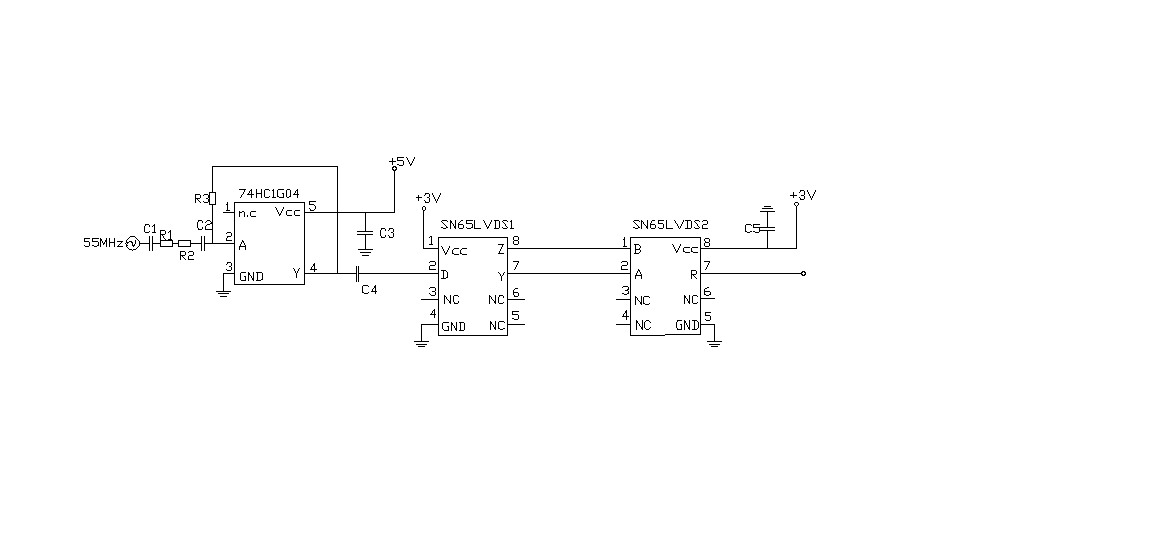
That’s the one in which the inverter have been mentioned above .I have the following questions:
First of all, what role does the inverter play? Does it transform the sine wave to square wave? Second, What role does the R3 play? How can I decide the value?
The last, What role does the part including SN65LVDS1 and SN65LVDS2 play? Can I use the signals in the output port of 74HC1G04 directly? What’s the advantages?
Thanks!
[/code]
This site uses cookies to help personalise content, tailor your experience and to keep you logged in if you register.
By continuing to use this site, you are consenting to our use of cookies.