Continue to Site

Welcome to EDAboard.com

Welcome to our site! EDAboard.com is an international Electronics Discussion Forum focused on EDA software, circuits, schematics, books, theory, papers, asic, pld, 8051, DSP, Network, RF, Analog Design, PCB, Service Manuals... and a whole lot more! To participate you need to register. Registration is free. Click here to register now.

Questions about Bandgap stability.

Status
Not open for further replies.

holddreams

Full Member level 6
Joined
Aug 2, 2005
Messages
351
Helped
15
Reputation
30
Reaction score
7
Trophy points
1,298
Location
Shanghai
Activity points
4,237
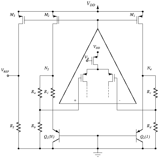
The attachment is the circuit of razavi's book ,figure 11.9.
My questions are:
1.How can I simulate the stability of this bandgap circuit?

2.Can we exchange the OPAMP input ?That is ,let the negative input connect with the A ,and the positive input connect with nA?

Thanks.
 

To check for the stability you need to perform the transient analysis, after adding in the start up circuit at different temperatures and then check if you get a stable output.
YOu cannopt exchange the terminals of the opamp since it would then become a positive feedback and the 2 nodes will not be forced to the same voltage.
 

you should open the loop, add a test source, do ac analysis to check the phase magin.
you couldn't exchange the 2 nodes of the opamp, it will introduce unstablity.
 

Wanily,

Where is the best place to break the loop and add a test source?
 

Breaking the loop and calculating the Phase MArgin is a good method to calculate the stability of a circuit by hand, but it is still a crude way and a circuit in some cases may be at the edge of instability even if it has a huge phase margin. So this way of finding the instability is useful to get idea about the instability.
To check if its really stable or not, you have to do a full transient analysis of the circuit. But if you do want to calculate the phase margin, the loop can be broken up at the output of the opamp and the loading effect of the resistors should be added. A test source should be applied at the point where the opamp output was connected.
 

aryajur said:
Breaking the loop and calculating the Phase MArgin is a good method to calculate the stability of a circuit by hand, but it is still a crude way and a circuit in some cases may be at the edge of instability even if it has a huge phase margin. So this way of finding the instability is useful to get idea about the instability.
To check if its really stable or not, you have to do a full transient analysis of the circuit. But if you do want to calculate the phase margin, the loop can be broken up at the output of the opamp and the loading effect of the resistors should be added. A test source should be applied at the point where the opamp output was connected.
Thanks, Aryajur.

Why do you say a transient analasys is needed? What results in the transient analysis should concern me regrding stability?
Which kind of input and where should I use for transient?
How can I calculate the size of the compensation capacitor I need to get enough phase margin by your suggestion?

Thanks,

Sharas
 

Any circuit may have many poles and zeros and maybe even some complex. How they interact with each other and give a system response can only be known accurately through a transient analysis. Bandgaps have instability mostly when they start up since the startup circuit provides a 'kick' to the circuit to come in the desired operating state. So you need to include the startup circuit to the bandgap and then just run the transient analysis, at different temperatures in your specified operating range, to check if the output is stable or not. Sometimes the output is stable at one temp but may be unstable at the other temperature.
If you see that you have instability then what you have to do is compensate the opamp. Now you need to idenfy the dominant pole node and calculate the compensation just like you would do for an opemp. For example for a single stage opamp you may want the compensation to be such that the dominant pole is so close to the origin that the unity gain frequency lies at the non dominant pole. Or if you have a 2 stage opamp you need to calculate the miller compensation capacitor.
 

aryajur said:
Breaking the loop and calculating the Phase MArgin is a good method to calculate the stability of a circuit by hand, but it is still a crude way and a circuit in some cases may be at the edge of instability even if it has a huge phase margin. So this way of finding the instability is useful to get idea about the instability.
To check if its really stable or not, you have to do a full transient analysis of the circuit. But if you do want to calculate the phase margin, the loop can be broken up at the output of the opamp and the loading effect of the resistors should be added. A test source should be applied at the point where the opamp output was connected.

(1)Can I simulate the transient analysis like this: .tran tstep tstop sweep temperature 0 85 1 ?
(2)Can you draw a circuit to show how to simulate the bandgap stability?That is where to put the test source ,and which is the output?
 

you cannot exchange the terminals of your opamp,you can find the answer in razavi's book.althrough the bandgap has a negative feedback loop and a positive feedback loop,you should confirm the overall circuit is a negetive feedback.if you exchange the terminals,the circuit would be a positive feedback.
 

holddreams said:
(1)Can I simulate the transient analysis like this: .tran tstep tstop sweep temperature 0 85 1 ?
(2)Can you draw a circuit to show how to simulate the bandgap stability?That is where to put the test source ,and which is the output?


Are you doing the simulation in HSpice? I don't think you can do a temperature sweep with a transient analysis like this. YOu have to run the transient analysis at different temperatures.
 

yes, I use hspice ,and .tran analysys can sweep the temperature at the same time.
 

The negative loop gain is higher than the positive loop gain. Now, I have a question:
Where do I measure the phase margin?? in the positive loop? or in the negative loop?? or in the two loops at the same time?? if anybody knew, pleas say to me how to measure the phase margin.

thanks in advance.
 

Hi jc2,
Phase margin always gives you a margin for the negative feedback loop to remain as a negative feedback. So you have to look at the main negative feedback loop of your circuit and break it at the appropriate point and then inject the AC signal there to calculate the phase margin of your negative feedback loop. As mentioned by steve_guo up the overall loop should be a negative feedback for proper stability.
 
  • Like
Reactions: jc2

    jc2

    Points: 2
    Helpful Answer Positive Rating
Hi jc2,
Phase margin always gives you a margin for the negative feedback loop to remain as a negative feedback. So you have to look at the main negative feedback loop of your circuit and break it at the appropriate point and then inject the AC signal there to calculate the phase margin of your negative feedback loop. As mentioned by steve_guo up the overall loop should be a negative feedback for proper stability.


Thank you aryajur. This is the circuit that i'm designing, where do you suggest to break the loop?. I broke the loop in the positive input of the OTA and put there the AC signal, and i measured the AC output voltage in the resistor Rb. Is that right?

thanks in advance.
 

Hi jc2,
Breaking the loop at the +ve terminal should be fine.
- I suppose Ra=Rc and Rb=Rd to keep the divider ratio the same and match well. But I don't understand why you need Ra,Rb,Rc and Rd. is it because your OTA won't take a higher common mode? The problem with this scheme is that you are introducing more error in your reference as compared to just tying the OTA inputs to the drains of the PMOS devices. That is because the OTA offset will now be multiplied by the resistor divider ratio and then appear across the nodes from where you have connected your dividers.
I guess you are using them to get a constant current in your PMOS devices to generate a constant reference at the output without using an extra diode. Is that they are there for?
 
  • Like
Reactions: jc2

    jc2

    Points: 2
    Helpful Answer Positive Rating
Hi jc2,
Breaking the loop at the +ve terminal should be fine.
- I suppose Ra=Rc and Rb=Rd to keep the divider ratio the same and match well. But I don't understand why you need Ra,Rb,Rc and Rd. is it because your OTA won't take a higher common mode? The problem with this scheme is that you are introducing more error in your reference as compared to just tying the OTA inputs to the drains of the PMOS devices. That is because the OTA offset will now be multiplied by the resistor divider ratio and then appear across the nodes from where you have connected your dividers.
I guess you are using them to get a constant current in your PMOS devices to generate a constant reference at the output without using an extra diode. Is that they are there for?

Thank you aryajur. Yes, I am using that resistor divider for being able to supply the OTA with a voltage lower than 1V without requiring low-threshold MOSFETs. I know the problem with the offset and with the OTA-input noise, but is a trade-off with the low-supply voltage.
And, yes, I'm using this topology for obtaining an output reference of less than the bandgap voltage at 0[K] (1.2V) , and in that way a sub-1V supply voltage.

Thank you!
 
Last edited:

Status
Not open for further replies.

Similar threads

Part and Inventory Search

Welcome to EDABoard.com

Sponsor

Back
Top