Continue to Site

Welcome to EDAboard.com

Welcome to our site! EDAboard.com is an international Electronics Discussion Forum focused on EDA software, circuits, schematics, books, theory, papers, asic, pld, 8051, DSP, Network, RF, Analog Design, PCB, Service Manuals... and a whole lot more! To participate you need to register. Registration is free. Click here to register now.

How to realise F = ~A*B + ~B*C using 4-input multiplexer...

Status
Not open for further replies.

student2005

Member level 3
Joined
Sep 23, 2005
Messages
57
Helped
2
Reputation
4
Reaction score
1
Trophy points
1,288
Activity points
1,793
Would someone pls show me how the function F = ~A*B + ~B*C could be realised using a 4-input multiplexer and some logic gates? Many thanks.
 

Do you think we can implement the function F with 2-input muliplexer? Thanks.

I have read the article, but still could not get the clue. Possible to show how a 4-input multiplexer could be used to implement the function F? Many thanks.
 

Re: How to realise F = ~A*B + ~B*C using 4-input multiplexer

F = ~A*B + ~B*C

If B=0, ~B=1, which means that ~A*B is always 0 and ~B*C depends on C. Hence F will only depend on C.
If B=1, ~B=0, which means that ~B*C is always 0 and ~A*B depends on ~A. Hence F will only depend on ~A.

So B is the select of the multiplexer and ~A and C are the inputs of the multiplexer. You can just use 2-input multiplexer.
 

lokeyh said:
F = ~A*B + ~B*C

If B=0, ~B=1, which means that ~A*B is always 0 and ~B*C depends on C. Hence F will only depend on C.
If B=1, ~B=0, which means that ~B*C is always 0 and ~A*B depends on ~A. Hence F will only depend on ~A.

So B is the select of the multiplexer and ~A and C are the inputs of the multiplexer. You can just use 2-input multiplexer.
Since 2-input multiplexer can do the job, so I think 4-input multiplexer sure will do the job as well, right?

If it's true, how am I going to configure the 4-input multiplexer in order to implement the function F mentioned above?

Many thanks...

Added after 4 hours 48 minutes:

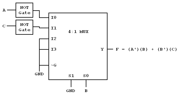
Pls advise whether the circuit configuration shown in the figure could implement the function F or not.

In my opinion, there are many ways to implement function F with ONE 4-to-1 MUX and additional logic gates. Am I correct? Pls advise. Thanks.

4-to-1MUX.gif
 

Re: How to realise F = ~A*B + ~B*C using 4-input multiplexer

dear student2005, i'm afraid that the config you've used for the 4:1 mux would not yield the desired function.
according to your design, when B=0 (and thus S1S0=00), IO is selected to give the output as (~A), while according to the function, the output must be C.
Similarly, when B=1, I1 is selected to give the output as (~C), while acording to the function, the output must be (~A).
So just connect I0 to C and I1 to ~A, with S1 grounded & S0 tied to B. That will give you the desired function.

There are many ways to implement a function using MUXs. An alternative way would be to choose A & B as the select lines, tying I0 & I2 to C, I1 to logic HIGH and I3 to GND. All this becomes clear when you write the truth table.

Hope this helps.
 
dear student2005, i hav read ur PM...reply u here...

my suggestion is tht u do the truth table for the boolean equation for the function:

Code:
F = ~A*B + ~B*C equivalent to 
F = ((NOT A) AND B) OR ((NOT B) AND C)

it is hard to use words to describe the behaviour of the equation... it is misleading n sometimes u will miss out something,,, so truth table please...and u will see clearly how the output respond to the input...

and then u can choose which to b ur select line & which to b ur inputs..

actually dont let the physical MUX output wth equation form confuse u... when u know wad type of outputs truth table is w.r.t ur inputs.... u can just output(verb here:) the desire output value according to ur truth table...

and again... we dont do homework for u here... u hav to help urself so tht we can help u...

warm regards,
sp
 

Re: How to realise F = ~A*B + ~B*C using 4-input multiplexer

you can also go this way

control bits [B,C] b:Most significant

I0=0 (Gnd)
I1=1 (Vdd)
I2=I3=~A
 

Don't worry, it's not a homework. I'm not in school anymore. When I have this problem, I have no one to ask and therefore I ask in this forum. Thank you guys...
 

Status
Not open for further replies.

Part and Inventory Search

Welcome to EDABoard.com

Sponsor

Back
Top