geo2020
Newbie level 4
I am trying to design a driver for a BLDC motor.
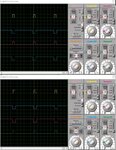
I have managed to generate 6 PWM signals with the PIC18F4431.
How I can shifted the phases?
I attach my code and the image of the PWM signals.

I have managed to generate 6 PWM signals with the PIC18F4431.
How I can shifted the phases?
I attach my code and the image of the PWM signals.
Code:
void pwm_inicialitze(void)
{
  PORTB=0x00;
  TRISBbits.TRISB0=0;
  TRISBbits.TRISB1=0;
  TRISBbits.TRISB2=0;
  TRISBbits.TRISB3=0;
  TRISBbits.TRISB5=0;
  TRISBbits.TRISB4=0;

  INTCON=0XC0;
  IPR3bits.PTIP=1;
  PIE3bits.PTIE=1;
  PIR3bits.PTIF=0;

  SEVTCMPL=0X00;
  SEVTCMPH=0X00;
  DTCON=8;
  FLTCONFIG=0X00;
  OVDCOND=0XFF;
  OVDCONS=0X00;

  PTMRL=0X00;
  PTMRH=0X00;
  PTCON0=0X00;
  PTCON1=0X80;
  PWMCON0=0X50;
  PWMCON1=0X01;
  PTPERL=124;
  PTPERH=0;

  PDC0L=60;
  PDC0H=0;
  PDC1L=60;
  PDC1H=0;
  PDC2L=60;
  PDC2H=0;
  PDC3L=60;
  PDC3H=0;

  ADCON0=0x00;
}

void main(void)
{
   ANSEL0=0X00;
   ANSEL1=0X00;
   pwm_inicialitze();
   while(1);
}