Continue to Site

Welcome to EDAboard.com

Welcome to our site! EDAboard.com is an international Electronics Discussion Forum focused on EDA software, circuits, schematics, books, theory, papers, asic, pld, 8051, DSP, Network, RF, Analog Design, PCB, Service Manuals... and a whole lot more! To participate you need to register. Registration is free. Click here to register now.

Stuck at simulations of Amplifier in LTSpice

Status
Not open for further replies.

robi10101298

Junior Member level 2
Joined
May 7, 2020
Messages
20
Helped
0
Reputation
0
Reaction score
0
Trophy points
1
Activity points
117
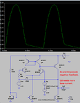
Hello, I need to simulate the following circuit in LTSpice. I made the scheme but I don't know what value to choose for R2 and Cinf in order to have theoretical gain Av=1500. The following constraints are imposed: Vcc=10v; VCM=1.5V; vg it's a sine wave with a frequency of 1Khz and R1=15kOhms. I need to simulate the circuit(transient, AC sweep), choosing an appropriate amplitude for vg in order to minimize output signal distortion(I put 100 uV but idk if it's correct..), and to specify a method for decreasing the voltage gain (without changing R1, R2, VCC or VCM). Implement the change and re-simulate the circuit in order to demonstrate the effect. Here it's the link for the LTSpice .asc scheme:

schema.PNG
 

Attachments

  • Project EDC.rar
    872 bytes · Views: 98

What you have is Vin = Vg = 100uV

What is the voltage value on resistor R1?
 

On the other website I noticed that the output coupling capacitor value is 1 Farad and will take weeks to charge so I reduced it to 0.1uf. Then I noticed that there is no negative feedback to set the DC operation point.
After adding negative feedback it still causes its bottom to have severe clipping.
 

Attachments

  • simulated amplifier.png
    simulated amplifier.png
    22.4 KB · Views: 187

the output coupling capacitor value is 1 Farad and will take weeks to charge so I reduced it to 0.1uf
Capacitors are zeroed during initial transient solution, thus a SPICE simulator has no problems with large capacitors, as long as the large signal operation point doesn't differ from the initial solution.

If clipping occurs, the circuit might take a long time to reach steady state.

- - - Updated - - -

Not sure if negative feedback is the intended way of the exercise problem to reduce gain. It's surely an option.

The schematic in post #4 has an error, the feedback voltage is shorted by the Vcm source.

- - - Updated - - -

Circuit with feedback could look like below. But consider, that the amplifier can't drive large output voltage into 15k load due to low class A bias current.

amp.PNG
 

Status
Not open for further replies.

Part and Inventory Search

Welcome to EDABoard.com

Sponsor

Back
Top