Continue to Site

Welcome to EDAboard.com

Welcome to our site! EDAboard.com is an international Electronics Discussion Forum focused on EDA software, circuits, schematics, books, theory, papers, asic, pld, 8051, DSP, Network, RF, Analog Design, PCB, Service Manuals... and a whole lot more! To participate you need to register. Registration is free. Click here to register now.

Will a filter block this waveform?

Status
Not open for further replies.

dl09

Full Member level 4
Joined
Feb 12, 2020
Messages
226
Helped
2
Reputation
4
Reaction score
1
Trophy points
18
Activity points
1,688
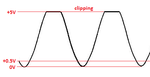
If the waveform begins at positive 0.5 volt,
Then increases to 5 volts, then decreases to
Positive 0.5 volt, then increases to 5 volts and has a
Frequency of 40 megahertz, will a passband
Filter with lower cutoff frequency of 100 megahertz and a higher cutoff frequency of
200 megahertz, block such a waveform?
 

What is the type of filter? bandpass or bandreject?
 

Since the waveform is not a sinewave then it has many harmonics at high frequencies. A multi-order lowpass filter is needed to block the 40MHz fundamental frequency and its harmonics.
Your idea to use a bandpass filter from 100MHz to 200MHz will block 40MHz but pass its 120MHz 3rd harmonic and 160MHz 4th harmonic frequencies.
 

When designing filters you need to specify the out of band performance, typically
a rejection number expressed in db

In this pic its the stopband Attn spec.

Bandpass Specs.gif

This spec typically helps determine the order of the filter you need.

The architecture has to handle, as previously mentioned, the harmonics of the 40 Mhz. Since you have
harmonics in passband of 100 - 200 Mhz one can think about using a combination of a HPF to get rid of
fundamental (40 Mhz) then traps (notch filter) at the output of the BPF to get rid of the two harmonics.

So HPF >> BPF >> Traps or just BPF >> Traps, depends on design and performance.

What is waveshape, Triangle ? How much harmonic suppression do you need ?

Is this a filter for COM work where you have to be concerned about phase response ?


Regards, Dana.
 
Last edited:

So if the waveform is not a sine wave it will
Produce harmonics?
 

Yes !

Spectra.jpg

You mighty study Fourier Transform as applied to signals to get insight.


Regards, Dana.
 
Last edited:

A filter cannot "block" any waveform. And a filter also cannot "block" frequencies.
It only can attenuate some unwanted frequencies - and as a consequence, it can only MODIFY or alter a waveform.
 

Hi,

So if the waveform is not a sine wave it will
Produce harmonics?

To be exact:
It already contains harmonics, it does not produce it.

Klaus
 
  • Like
Reactions: dl09

    dl09

    Points: 2
    Helpful Answer Positive Rating
So I built an FM transmitter not that long
Ago, I tested it with a spectrum analyzer.
I used a 100 mhz crystal oscillator. Finally got a crystal oscillator working.
There were spikes at 100 mhz and there spikes at other frequencies. So if i use a bandpass filter I can filter the harmonics and not get spikes at other frequencies? I am using my dad's phone and don't have a lot of time to use it, but I will post a schematic as soon as I can.

- - - Updated - - -

So it consist of a monopole antenna, a crystal oscillator, and a battery. And here is a schematic.

- - - Updated - - -

20200522_090631.jpg here it is the schematics.
 

So you have signals of interest from 100 - 200 Mhz.

You have a 40 Mhz signal you want to get rid of.

The BPF will get rid of the 40 Mhz, depending on your rejection specs and the order
of the filter. But it will pass the 120 Mhz, 160 Mhz harmonic of the 40 Mhz signal.

So you then need traps (another form of filtering), to get rid of those. Note if there
is a legit 120 or 160 Mhz signal the traps will get rid of those as well. Filters cannot
discriminate between two different signals one legit, one a harmonic, who both are
on the same freq.


Regards, Dana.
 

Does The 100 mhz crystal oscillator produce any frequencies other than 100 mhz? According to the datasheet the waveform starts at positive 0.5 volt then increases to 5 volt, stays at 5 volts for a short time, then decrease to positive 0.5 volt, then increases to 5 volts, stays at 5 volts for a short time, then decreases to positive 0.5 volt and on and on.
 

Your waveform description is useless to determine its harmonic content. What you are describing could be anything.

A scope image or better still a spectral analysis is required to answer your questions.
 

You describe a sinewave that has clipping like this:
 

Attachments

  • sinewave with clipping.png
    sinewave with clipping.png
    11.9 KB · Views: 111

So I built an FM transmitter not that long
Ago, I tested it with a spectrum analyzer.
I used a 100 mhz crystal oscillator. Finally got a crystal oscillator working.
Does not compute Will Robinson. (with apologies to 'Lost in space' fans). A crystal oscillator generally can't be used for FM transmission.

I'm guessing you used a crystal oscillator module, probably of the type used for clock generation so the output would be substantially a square wave. The 5V reference suggests it has TTL output. The harmonic output will be huge, you really need either low pass filter with a large out of band attenuation or better still a resonant circuit that only accepts a single frequency rather than rejecting the many unwanted ones.

Brian.
 
  • Like
Reactions: dl09

    dl09

    Points: 2
    Helpful Answer Positive Rating
Does not compute Will Robinson. (with apologies to 'Lost in space' fans). A crystal oscillator generally can't be used for FM transmission.

I'm guessing you used a crystal oscillator module, probably of the type used for clock generation so the output would be substantially a square wave. The 5V reference suggests it has TTL output. The harmonic output will be huge, you really need either low pass filter with a large out of band attenuation or better still a resonant circuit that only accepts a single frequency rather than rejecting the many unwanted ones.

Brian.

so if I use a 100 mhz crystal oscillator module
It produces many harmonic frequencies?
 

so if I use a 100 mhz crystal oscillator module
It produces many harmonic frequencies?
Not necessarily, but probably.
If the module produced a pure sine wave output it would not have any harmonics. A sine wave is a single frequency. If the output is not a sine wave, even with the smallest of imperfections it does have harmonics.
Most crystal modules are designed for driving digital circuits where the rate the edges rise and fall is important and they are optimized to make the rise and fall times as short as possible. That means their output is more like a square wave than a sine wave and as you can see from the spectrum graphs in post #6, there will be lots of harmonics.

Note that harmonics are not a side effect of having an impure waveform, they are a component part of the wave shape. For example, you cannot make a square wave that doesn't have harmonics.

Brian.
 

I looked at the datasheet, the crystal oscillator module that I use, does not produce sine wave. I connected it to an antenna and a battery, making a radio transmitter. I tested it with spectrum analyzer, i saw spikes at 100 mhz and other frequencies. Would electronic filters eliminate those spikes and i only get a spike at 100 mhz?
 

How will you Frequency Modulate (vary the frequency) the single frequency to make FM?
Years ago, Silicon Chip magazine published The Micromitter FM stereo transmitter project and a kit for it was sold in Australia. It used a 7.6MHz crystal and electronics to make 4 radio frequencies without any harmonics. The BH1417 IC is listed at Digikey but they have none anymore.
 

Attachments

  • 30378_14lo.jpg
    30378_14lo.jpg
    33.3 KB · Views: 100

I looked at the datasheet, the crystal oscillator module that I use, does not produce sine wave. I connected it to an antenna and a battery, making a radio transmitter. I tested it with spectrum analyzer, i saw spikes at 100 mhz and other frequencies. Would electronic filters eliminate those spikes and i only get a spike at 100 mhz?

Yes, if you do a narrow band filter for 100 Mhz that would suppress out of band mstuff.

To do a LC design - https://rf-tools.com/lc-filter/


Regards, Dana.

- - - Updated - - -

Here is an example -

100 Mhz BPF.JPG


Regards, Dana.
 

How will you Frequency Modulate (vary the frequency) the single frequency to make FM?
Years ago, Silicon Chip magazine published The Micromitter FM stereo transmitter project and a kit for it was sold in Australia. It used a 7.6MHz crystal and electronics to make 4 radio frequencies without any harmonics. The BH1417 IC is listed at Digikey but they have none anymore.

As long as I can build a receiver to detect radio waves I will be happy

- - - Updated - - -

Yes, if you do a narrow band filter for 100 Mhz that would suppress out of band mstuff.

To do a LC design - https://rf-tools.com/lc-filter/


Regards, Dana.

- - - Updated - - -

Here is an example -

View attachment 159511


Regards, Dana.

So if I connect the transmitter to a narrow band filter that would eliminate the spikes at other frequencies?
 

Status
Not open for further replies.

Part and Inventory Search

Welcome to EDABoard.com

Sponsor

Back
Top