Continue to Site

Welcome to EDAboard.com

Welcome to our site! EDAboard.com is an international Electronics Discussion Forum focused on EDA software, circuits, schematics, books, theory, papers, asic, pld, 8051, DSP, Network, RF, Analog Design, PCB, Service Manuals... and a whole lot more! To participate you need to register. Registration is free. Click here to register now.

TMR 6-0523 does not start

Status
Not open for further replies.

el00

Member level 5
Joined
May 27, 2009
Messages
80
Helped
0
Reputation
0
Reaction score
0
Trophy points
1,286
Activity points
2,156
Hello, I have a pcb that is already functional, however I have a problem with a section powered by a TMR 6-0523 which does not like the board, apparently.
The load consists in a lot of audio amplifiers which in total draw about 3.5W. There is about 20uF of total capacity in parallel to the load, but according to Traco datasheet the maximum capacitance on each rail is 600uF, so there should be no problem.
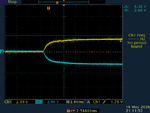
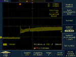
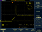
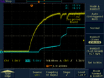
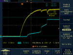
I also added 100uF in parallel to the input. No luck. The DC converter does not start, it is stuck at about +/-3V.
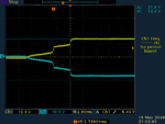
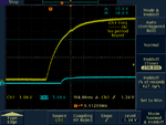
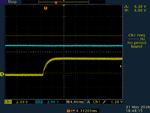
But, if It add 24ohm (or more) in series to the outputs (two resistors, each for rail) then it works. It behaves as if there is too much capacitance, which is not, according to datasheet, so I do not understand what is the problem.
Now, having that resistance in series for a test is ok, but it is not acceptable so I decided use a LR (L in parallel to R) in series to the outputs. I tried to use a combination of 1mH parallel 24ohm, no luck. Tried 300uH parallel 24ohm, no luck. Tried to replace 24 with 27ohm, no luck.
What do you suggest?
 

The TMR6-0523 can only deliver 200mA. You do not say what your 'lot of audio amplifiers' consist of, do they draw any additional start-up current to charge capacitors?

Brian.

- - - Updated - - -

The TMR6-0523 can only deliver 200mA. You do not say what your 'lot of audio amplifiers' consist of, do they draw any additional start-up current to charge capacitors?

Brian.
 

The TMR6-0523 can only deliver 200mA. You do not say what your 'lot of audio amplifiers' consist of, do they draw any additional start-up current to charge capacitors?
The capacitors are only bypass, required by the datasheets of the audio amplifiers. The output of the audio amplifiers is going to high impedance (in practice they work as preamplifiers, there is another board that handles the power amplifiers).
The total power is 3.5W, as I said. That is the sum of all audio amplifiers power requirement, so the DC should do the job, and in fact it does it in steady state, but there is nothing special in the audio amplifiers during the startup, given that they have no load connected (and if any, it is high impedance).
 

Hi,

use a scope to measure the startup currents (if possible, the voltages, too) on both rails.

Klaus
 

TEK00000.PNG is taken with 24ohm resistors (both rails): the DC gets to 15V per rail
TEK00001.PNG image is taken without 24ohm resistors: the DC is stuck at <3V per rail

Measuring the currents on the output... without the resistors I am not sure how to do that. What do you suggest?
 

Attachments

  • TEK00000.PNG
    TEK00000.PNG
    10.7 KB · Views: 102
  • TEK00001.PNG
    TEK00001.PNG
    12.7 KB · Views: 105

Hi,

without the resistors I am not sure how to do that. What do you suggest?
* A low ohmic resistor (1 Ohm or less)
* a current probe
* a current transducer (LEM)
...


Klaus
 

Hi,


* A low ohmic resistor (1 Ohm or less)
* a current probe
* a current transducer (LEM)
...


Klaus

Well... to place a current probe inside an assembled PCB is not the easiest thing... However, I managed to do the measurement of the voltage across the series resistor. Attached you see:
1) the voltage drop across 24 ohm: the steady state current is 75mA, in this situation the DC converter is working because the series resistor is limiting the current during the transient (refer to voltage TEK00000.PNG in post #5)
2) the voltage drop across 4 ohm: the steady state current is 45mA, the DC is not working, it does not even try to raise the voltage (refer to voltage TEK00001.PNG in post #5)

It is quite obvious that limiting the current with a resistor the DC starts. But, it is less obvious why the DC does not start with a R parallel L in series, with L = 1mH.

What should I try next?
 

Attachments

  • TEK_4OHM.PNG
    TEK_4OHM.PNG
    15.5 KB · Views: 110
  • TEK_24OHM.PNG
    TEK_24OHM.PNG
    12 KB · Views: 112

Hi,

When I see it correctly, then on the first picture the current peaks twice to 500mA.

This may be too high.

May we see all the circuit driven by the DCDC converter?

Klaus
 

Hi,

When I see it correctly, then on the first picture the current peaks twice to 500mA.

This may be too high.

May we see all the circuit driven by the DCDC converter?

Klaus

The part of the circuit driven by the DCDC is a Sallen Key lowpass with a gain o 2, very standard design, each fet amplifier has 0.1uF bypass per rail, and the output goes to a DRV135UA, which has 1uF per rail, and whose output is unconnected (it goes to an external connector).
This circuit is repeadted N times. Nothing else.
The circuit is working, in fact when I use the 24ohm in series I can test and operate the circuit correctly, it does what it is supposed to do.
 

Klaus,
the circuit is attached. Repeated x 16.
 

Attachments

  • single_channel.jpg
    single_channel.jpg
    61.3 KB · Views: 100

Hi,

I' d rather expect 100mA than 75mA steady current.
When you connect load it may be more.

What about the input voltage to the TMR .. is it stable during start up?

Klaus

(Note: "FROM ADC" should be "FROM DAC", isn´t it?)
***

BTW: do you want it to be high quality audio?

Klaus
 

Hi,

I' d rather expect 100mA than 75mA steady current.
When you connect load it may be more.

What about the input voltage to the TMR .. is it stable during start up?

Klaus

(Note: "FROM ADC" should be "FROM DAC", isn´t it?)
***

BTW: do you want it to be high quality audio?

Klaus

oK I think I found the problem. If you look at the attachment TEK_IN_OUT.PNG, you see that there are two peaks in the input voltage (yellow, the blue is positive output).
This is WITH 24ohm resistors. Without it will be worst and will cause hiccup since it will bring the input voltage below the critical threshold.
I already have 147uF in parallel to the input, but it appears that they are not enough. I have some space on the board, so I will try to increase input capacitance to 1000uF or more if necessary, and reduce the 24ohm to a lower value. I cannot leave such a large resistor in series.
Still surprised why I did not solve with inductors, though.
What do you think?


Quality? It's ok as far as I measured, for my needs.

- - - Updated - - -

I was wrong. Increasing from 150uF to 650uF input capacitance did not help.
See attachments: with 24ohm still ok, with 4ohm series it does not start. But now I see no justification for that.
Tried with 18ohm instead of 24, still does not work... despite the large input capacitance.... very strange
At the moment I do not have larger capacitors. To try more input capacitance it will take time. Not sure it will solve, at this point
 

Attachments

  • TEK_IN_OUT.PNG
    TEK_IN_OUT.PNG
    16 KB · Views: 97
  • TEK_650uF_24OHM.PNG
    TEK_650uF_24OHM.PNG
    14.4 KB · Views: 94
  • TEK_650uF_4OHM.PNG
    TEK_650uF_4OHM.PNG
    14 KB · Views: 102

Hi,

I agree it may/should be solved on the primary side. ... without series resistors.

Steady input current will be about 600mA, but the inrush current may be much higher.
That´s why they recommend an input fuse of 3.5A slow blow.

These peak inrush currents call for a low impedance input path. Lengthy or thin wires, any series impedance like fuses, overcurrent protections, filters and so on will cause a voltage drop. Maybe too much voltage drop.

Since all happens at ther very beginning of power up, when your 5V is not really stable yet.
You could also use the REMOTE input of the TMR: let the input voltage stabilize, then enable the TMR. This may or may not help. But maybe worth a try.

Klaus
 

Hi,

A poor sticking plaster solution could be to start up with the 24R resistor at the output and when Vout is at the right value switch it out. 1 comparator controlling an NMOS + resistor path and a PMOS after power good (ignoring pesky body diodes and need for back-to-back MOSFETS) . That would be better with load switch/power path ICs.

Do you think the impedance of the source for the DC-DC converter could be the cause of the problem? Or that thing about a DC-DC converter being a negative impedance to the source? I'm just learning about that stuff.
 

Hi,
[...]
Since all happens at ther very beginning of power up, when your 5V is not really stable yet.
You could also use the REMOTE input of the TMR: let the input voltage stabilize, then enable the TMR. This may or may not help. But maybe worth a try.

Klaus
I start thinking that this model of DC converter is not reliable.
I soldered a switch on the remote. If I wait that everything is stable and then open the switch (enabling the DC), as you see it does not start (in the case without the 24ohm in series). The input voltage is the blue trace: it is perfect. But, it does not work: it is stuck at <3V.
I am thinking ordering another model. It is really frustrating, I do not think the problem is my circuit at this point. But the consequence is that I have to do heavy modification to a PCB, which is very disappointing... unless I solve with a pin2pin compatible competitor model. Very strange, I had problems with Recom but never had problems with a Traco.
 

Attachments

  • TEK_WITH_REMOTE.PNG
    TEK_WITH_REMOTE.PNG
    12.1 KB · Views: 93

Hi,

I start thinking that this model of DC converter is not reliable.
...means "guessing". I agree. But you don´t need to guess.

A scope view of both output currents (and voltages) could give solid informations whats really happening. (as already meantioned in post#4)
A test - off the PCB - just with capacitors and a 150mA load at each rail could give solid informations.

There is a chance that the TMR does not work with your load. So why not find it out?

*****
It shouldn´t be too much effort (compared to the hours that you already invested) to desolder the DCDC and add two 1 Ohm resistors to measure the current.

*****

A photo of your circuit, a couple of pictures of your PCB layout could also help to find some issues. If not .. what do you have to lose?


Klaus
Klaus
 

Status
Not open for further replies.

Similar threads

Part and Inventory Search

Welcome to EDABoard.com

Sponsor

Back
Top