Continue to Site
Follow along with the video below to see how to install our site as a web app on your home screen.
Note: This feature may not be available in some browsers.
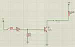
your load current is approx. 6mA.
TIP122 required for this current?
Hi,
internet search for "current limit open collector circuit" should give some ideas.
Klaus
--> there are hundreds, maybe thousandsI could not find
--> how else do you want it?generally they are for constant current limit
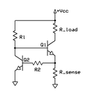
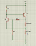
--> No, just a resistor for current measurement is at the emitter, load is at collectorthe load is at the emitter side.
Hi,
--> there are hundreds, maybe thousands
--> how else do you want it?
--> No, just a resistor for current measurement is at the emitter, load is at collector
Klaus
Hi,
if the current limit is not sufficient...
How much foldback do you want?
A complete down to zero or just partly reduce? To what level? What timing? How to go back to normal operation?
A drawing could be helpful.
Klaus