Continue to Site

Welcome to EDAboard.com

Welcome to our site! EDAboard.com is an international Electronics Discussion Forum focused on EDA software, circuits, schematics, books, theory, papers, asic, pld, 8051, DSP, Network, RF, Analog Design, PCB, Service Manuals... and a whole lot more! To participate you need to register. Registration is free. Click here to register now.

Bridge rectifier circuit.

Status
Not open for further replies.

paardenvlees

Newbie level 4
Joined
May 14, 2020
Messages
6
Helped
0
Reputation
0
Reaction score
0
Trophy points
1
Activity points
66
Hi,

I have an output with 230Vrms 50 Hz.
I want to put a diode bridge rectifier after it and then with an electronic load(2.3kW or 10A)

The used equations are from this page: https://www.electronics-tutorials.ws/diode/diode_6.html?utm_referrer=https://www.google.com/
The calculation of the rectifier max output is:
Vmax = Vrms * sqrt(2) - Vf
Vmax = 230* sqrt(2) - 1.1
Vmax = 324V

Vaverage = 2*Vmax /pi = 206V

capacitance = Iload/(Vrip*Hz) = 10/(5*50) = 0.04F
The system is simulated in proteus and i get a perfect 230V max voltage output.
Is the simulation just doing the most ideal or did i do some wrong calculations?


Further I am in doubt how to add the load to the system.
I can do constant power and constant current and constant resistance. I don't know what the best choice is in this situation.

Simulation setup:
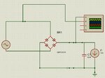
Capture.JPG
 

Hi,

The system is simulated in proteus and i get a perfect 230V max voltage output.
Is the simulation just doing the most ideal or did i do some wrong calculations?
Line voltage is given in 230V RMS, this is 325V peak = 325V amplitude = 650Vpp

Often simulator AC voltages are set as "amplitude" not RMS. Check whether you set up simulator voltage correctly.

I can do constant power and constant current and constant resistance. I don't know what the best choice is in this situation.
Usually you should have an idea what you want to simulate....
Set up the simulation most close to the real circuit.
If this real circuit has constant current behaviour, then use a constant current load ... and so on....

Klaus
 

haha yes i saw it. So i leave it.

I now build a three phase diode brigde circuit. When i for example put 20A load to it the current at the AC side is about 3.7kA for one phase?
When i do this with a one phase circuit bridge the load is just 20A like the DC current.

What is the relation between the AC current and the current at the DC side?
This is the circuit:
Capture.JPG
 

Hi,

There are two GND symbols in your circuit.....causing a short circuit.
The "high" current flows through D4, D5, D6...

Klaus
 

ahh I see. I fixed it.

Now I get 16.3A at one phase.
How does it comes to this value? How can i calculate the AC current?
Capture.JPG
 

Hi,

Currents...
It's not that simple ... especially in this case...

Look at the currents with a scope.

Klaus

Added:
The load is a constant 20A current. All the time exactly 20A.

But the load in the line is 1/3 of time positive constant 20A current and 1/3 of time negative constant 20A current.
The Amperemeter shows RMS current. Since with RMS current calculation all currents are squared it does not matter whether it is positive or negative.
So it's 1/3 negative and 1/3 positive makes 2/3 of time x 20A constant current.
We have 2/3 of duty cycle.
RMS current is sqrt(2/3) x constant current = sqrt(2/3) × 20A = 0.8165 x 20A = 16.323A

Klaus
 

Status
Not open for further replies.

Similar threads

Part and Inventory Search

Welcome to EDABoard.com

Sponsor

Back
Top