FreshmanNewbie
Full Member level 6
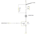
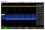
I have a buzzer circuit. Attached my schematics and the waveform.
Please have a look at the schematic attached. Also mentioned where I am measuring the values.
My questions :
1. I have marked the points in the circuit where I am measuring the voltage and the current. PWM pulse is given to the base of the transistor. I want to understand why the voltage waveform is like that and the current waveform is like that? Why is the voltage waveform Flat and the current waveform like spiked?
2. I would like to understand, only what will happen if I keep increasing the PWM pulse width at the base of the transistor. Please help me understand. (I don't write codes which is why I would not be able to check this by varying the PWM output coming from the Microcontroller to the base of the transistor)