Continue to Site

Welcome to EDAboard.com

Welcome to our site! EDAboard.com is an international Electronics Discussion Forum focused on EDA software, circuits, schematics, books, theory, papers, asic, pld, 8051, DSP, Network, RF, Analog Design, PCB, Service Manuals... and a whole lot more! To participate you need to register. Registration is free. Click here to register now.

Voltage reference for ADC

Status
Not open for further replies.

FreshmanNewbie

Full Member level 6
Joined
May 10, 2020
Messages
385
Helped
0
Reputation
0
Reaction score
2
Trophy points
18
Activity points
3,843
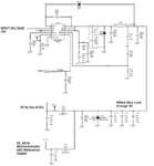
There's a 5V DC-DC Regulator in my reference schematic. Step downs from 12V to 5V. Schematic is attached below.

The 5V output is divided into two branches. One 5V branch is the Vcc for some ICs and a microcontroller.

The other 5V branch, is given as the voltage reference for the ADC port in the microcontroller.

Why is this done? Why can't we merge both the 5V output as one?

Maybe because the output 5V which is the Vcc for the other ICs may vary because the load current in that rail may vary?
 

Attachments

  • Capture.PNG
    Capture.PNG
    128 KB · Views: 100

Hi,

* One "dirty" 5V for power supply.. with noise maybe with voltage drop according load
* the other "clean" as ADC reference.

You need to understand that the digtal value of an ADC output depends the same magnitude on VRef (and it´s noise) as the Signal input.
Thus if you have 5% uncertainty (noise, thermal drift...) in the ADC_Ref you will get 5% uncertainty in the digital value.

And you need to know that usually a power supply voltage is not stable. It is made to supply circuitry with power. For a power supply it is no problem if there is 5% noise or thermal drift or drift according load current.
But for the ADC result it matters.

It does not matter how good an ADC is or how many bits of resolution it has ... when it uses VCC as voltage reference the digital result will not be better than those of any random 8 bit ADC.

Klaus
 
  • Like
Reactions: ats2

    A

    Points: 2
    Helpful Answer Positive Rating
there is only an LC filter between the two outputs.
clean is cleaner than dirty, but maybe not so clean as one might think or want as a reference for an ADC.

does the reference have to be 5V?
since the reference will likley draw very little current, you might find a 5 V reference that will run properly at 12 v +/- 5%
put a resistor in series and a capacitor in parallel and you'll have a much better reference.

you might consider this
Its from Analog Devices, so it does what the spec sheet says
it is also significantly better as a reference than the "clean' circuit

https://www.digikey.com/product-detail/en/analog-devices-inc/ADR293GRZ/ADR293GRZ-ND/998070
 

Hi,

* One "dirty" 5V for power supply.. with noise maybe with voltage drop according load
* the other "clean" as ADC reference.

You need to understand that the digtal value of an ADC output depends the same magnitude on VRef (and it´s noise) as the Signal input.
Thus if you have 5% uncertainty (noise, thermal drift...) in the ADC_Ref you will get 5% uncertainty in the digital value.

And you need to know that usually a power supply voltage is not stable. It is made to supply circuitry with power. For a power supply it is no problem if there is 5% noise or thermal drift or drift according load current.
But for the ADC result it matters.

It does not matter how good an ADC is or how many bits of resolution it has ... when it uses VCC as voltage reference the digital result will not be better than those of any random 8 bit ADC.

Klaus

Thank you. I am not clear when you say about clean and dirty.

Since both the 5V supply (to the other loads and the ADC reference, come from the same 5V regulator output. So, if voltage drops in one rail, there might be a drop in the other rail too?

And when you say noise might affect the dirty 5V rail, how will noise affect only the dirty 5V rail and not the clean 5V rail?
 

Why should we use a resistor instead of an inductor? And how to pick the value of the resistor?

- - - Updated - - -

Hi,

* One "dirty" 5V for power supply.. with noise maybe with voltage drop according load
* the other "clean" as ADC reference.

You need to understand that the digtal value of an ADC output depends the same magnitude on VRef (and it´s noise) as the Signal input.
Thus if you have 5% uncertainty (noise, thermal drift...) in the ADC_Ref you will get 5% uncertainty in the digital value.

And you need to know that usually a power supply voltage is not stable. It is made to supply circuitry with power. For a power supply it is no problem if there is 5% noise or thermal drift or drift according load current.
But for the ADC result it matters.

Klaus

Yes, I understand your second section of your answer. But when you say, clean and dirty, I understand that clean means without any voltage fluctuations or variations and dirty means, with voltage fluctuations or ripples.
But What am I not getting is that, how is the clean achieved just by taking out a separate 5V branch from the SAME 5V main output?

How is this clean voltage line achieved just by taking it out from the main branch?

Please help me clear these doubts.

My thoughts:

When the voltage drops in the dirty 5V branch due to high current in short time, this 5V may also reflect in the main regulator output which feeds the clean 5V right? So, clean 5V also gets affected right?

- - - Updated - - -

Hi,

* One "dirty" 5V for power supply.. with noise maybe with voltage drop according load
* the other "clean" as ADC reference.

Klaus

How is the clean and dirty achieved in each branch when both have the same capacitor and ferrite bead component with same values?

If the "dirty" 5V branch have a voltage drop due to high current, won't this also affect the "clean" 5V (as the "dirty" & "clean" 5V rail both come from the same MAIN 5V Regulator output)?
 

Hi,

At the "dirty" path there are microcontrollers and other digital circuits. They cause the "dirt". They draw short spikes of current, causing high frequency noise. One time they draw more current next time they draw low current depending on code, this causes lower frequency noise.

The power supply will drift with load current, time and temperature. We can't prevent the power supply from drifting with time and temperature. But with the filter between dirty path and power supply we just reduce the high frequency influence of the digital noise. The low frequency noise will go back to the power supply.

Now to the "clean" path. It is fed from the power supply. The power supply is - due to the filter to the dirty path - more clean...and the filter to the clean path makes it more clean.

, I understand that clean means without any voltage fluctuations or variations
This you misunderstood.
It is by far not free from fluctuations. All the lower frequency fluctuations caused by temperature and time can't be filtered out and thus still remain.
But the higher frequency noise is attenuated. The ADCresult is more clean now... from sample to sample.
But if you do the same measurement now and an hour, a day, a year later ... it will still drift. Drift a lot.

The way of the HF dirt is: digital section --> filter --> power supply section --> filter --> analog section.

This describes just one source of noise. For sure there are many other. Like EMC caused noise, currents in the ground plane, power supply noise (SMPS) and many others ...

Klaus
 
Hi,

How is the clean and dirty achieved in each branch when both have the same capacitor and ferrite bead component with same values?

the ferrite bead is usually chosen in accordance with the SMPS switching frequency, thus representing a high impedance for the SMPS switching frequency and a low impedance at DC. But the ferrite bead only isolates the SMPS switching noise, as KlausST explained, the noise on each supply branch depends (amongs others) on the attached devices (analog / digital / high power).

greets
 
So, If my SMPS Switching frequency is 248kHz, my ferrite bead should have high resistance around 248kHz, right?
 

Hi,

yes exactly. Althoug for 248 kHz it might be difficult to get an appropriate rated ferrite bead. Have a look at e.g. Digikey, maybe a ferrit bead with a rated impedance @ 1 MHz will do the job. Have a look in the datasheet, often there is a impedance vs. frequency plot, at least for ferite beads from Wuerth. Keep the current handling capability and the DC resistance value in mind.

For SMPS operating at higher frequencies e.g. easy switchers from TI (e.g. LMZ10505 @ 1 MHz) there is more variety by means of more available ferrite beads rated at higher frequencies.

greets
 
Last edited:
Status
Not open for further replies.

Part and Inventory Search

Welcome to EDABoard.com

Sponsor

Back
Top