Continue to Site

Welcome to EDAboard.com

Welcome to our site! EDAboard.com is an international Electronics Discussion Forum focused on EDA software, circuits, schematics, books, theory, papers, asic, pld, 8051, DSP, Network, RF, Analog Design, PCB, Service Manuals... and a whole lot more! To participate you need to register. Registration is free. Click here to register now.

Frequency Response of LC Filter has a Peak with an Impedance Load

Status
Not open for further replies.

Nurahmed

Junior Member level 1
Joined
May 27, 2019
Messages
19
Helped
1
Reputation
2
Reaction score
1
Trophy points
3
Location
Montreal, Canada
Activity points
172
Hi,

I am designing an LC filter with a cut-off frequency of 20 kHz for the Class-D amplifier. The filter schematic is shown in Fig.1 top right. I understand how to choose the LC values for the critically damped case for the pure resistive load as shown in Fig. 2.

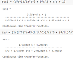
The problem is I want to drive an impedance (400 Ohm + 15 mH) load, where the transfer function becomes a 3rd order, and it has a zero too (Fig.1). The frequency response has a peak for impedance load as shown in Fig.3 & Fig.4. The pole-zero map for impedance load is shown in Fig.5. The transfer function with values for impedance load in MATLAB is also shown in Fig.6.

How can I reduce the quality factor (peak) for this impedance load? How can I find out the quality factor (or damping ratio) for the 3rd order system?
(The problem is the complex poles and the real pole are close together, so I cannot approximate the 3rd order system with the 2nd order system where I can easily write down the damping ratio expression).
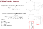
Fig.1 Transfer function_LC filter.png
Fig.1 LC filter & transfer function

Fig. 2 LC values for critically damped_LC filter.png
Fig.2 LC values calculation for critically damped filter for resistive load
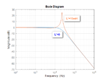
Fig.3 Bode_LC filter.png
Fig.3 Frequency response of LC filter with resistive & impedance load

Fig. 4 LTspice_LC filter.png
Fig.4 Frequency response of LC filter with resistive & impedance load (LTspice)
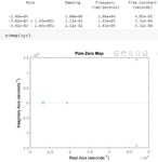
Fig 5. PoleZero_LC filter.png
Fig.5 Poles & Pole-Zero map

Fig. 6 Matlab Transfer function_LC filter.png
Fig.6 Transfer function of 3rd order filter with values in MATLAB
 

Hi,

with your inductive load your are creating a LC resonance circuitry, and as the quality factor of a LC circuit is defined as [1, page 26]

Q = 1/R • √(L/C)

your resistance of 400 Ω should already improve the dampening at your resonance frequency. A possibility to reduce the resonance peaking would be to introduce an additional series resistor with C_BTL1, which would dissipate energy (reduces Q). Or, you desige your filter resulting in a low C_BTL1, which shifts the peaking towards higher frequencies (but does not damp it).

BTW, increase your number of points per decade in LTspice, because actual your resonance peaking should be even larger.

[1] https://tiij.org/issues/issues/winter2010/files/TIIJ%20fall-winter%202010-PDW2.pdf

greets
 
Hi,

Thanks for the reply. I added a series resistor with C_BTL, so it does reduce the peak. But lower C_BTL increases the peak, so I increase the C_BTL instead of reducing it.

After adding a series resistor with C_BTL, the system becomes the 4th order. The transfer function becomes very complex. Good thing is that two poles and two zeros are close together & cancelled each other, and only left two complex poles, which render the filter response looks like a 2nd order filter.

The problem is, I can choose component values that depend on simulation results. But I want to derive a damping ratio equation of the whole filter circuit from this transfer function, then choose component values based on calculations. Any suggestions on that? (I am an academic person, so I need to calculate rather than depending on simulation results).

Add Rc.png

Increase C_BTL.png

Increase Rc.png

LC TF_Added Rc.png

LTspice.png
 

Hi,

what do you mean with damping ratio equation? Do you mean the damping ratio defined by [1]

ξ = 2/Q

So to avoid a peaking Q should be below 0.707. I assume that should be your target, I'm right?

[1] https://www.analog.com/media/en/training-seminars/tutorials/MT-210.pdf

You are right. The Q factor can be extracted from the transfer function, right. E.g. the second-order system mentioned in the reference you sent, the Q factor appears in the coefficient of "s". So in my case, the 4 order, how do I find the Q factor so that I can set the Q=0.707, cut-off frequency of filter fc=20kHz to calculate the LCR values of the filter.

Thanks.
 

Q is a parameter of the complex pole pair respectively the second order filter building block. A 4th order filter can't be described by a single Q number.

A reasonable way is to choose a filter prototype, e.g. Bessel, Butterworth or Chebychev with intended characteristic and implement this filter for the given source and load impedance. Unfortunately, the filter characteristic can't be preserved when changing the impedances.
 
How can I reduce the quality factor (peak) for this impedance load? How can I find out the quality factor (or damping ratio) for the 3rd order system?

Quality factor for an oscillator depends on the loading. For all practical purposes, loading should be considered dissipative. For example, R is a dissipative element whereas L and C are not.

Damping of a typical oscillator can be done by using increased dissipation. For a regular (harmonic oscillator) we use a term critically damped (vs under and over damped) dissipation.

Therefore if you increase the resistive component of the load, you decrease the Q and the peak. But I guess you should look for the critically damped solution.

You have provided the impedance map (poles are the singular points and you must avoid operation close to a pole).

Or I have not followed your question at all.
 

Status
Not open for further replies.

Part and Inventory Search

Welcome to EDABoard.com

Sponsor

Back
Top