Continue to Site

Welcome to EDAboard.com

Welcome to our site! EDAboard.com is an international Electronics Discussion Forum focused on EDA software, circuits, schematics, books, theory, papers, asic, pld, 8051, DSP, Network, RF, Analog Design, PCB, Service Manuals... and a whole lot more! To participate you need to register. Registration is free. Click here to register now.

Is my Schematics Ok?

Status
Not open for further replies.

kowshik1729

Newbie
Joined
May 10, 2020
Messages
3
Helped
0
Reputation
0
Reaction score
0
Trophy points
1
Activity points
32
Hello guys,

I have developed a design with Espressif products and I attached the schematic in the attachments.
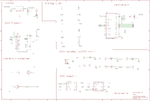
review_schematic.png

I need thoughts on following things

1. Is my Rx and Tx toggling LED's connections are correct?

2. As I made voltage coming from USB as the common power source, will it be able to drive the whole circuit on the board? (This is my major concern) Please let me know.

3. The Io0 and EN toggling circuit is correct? I made this in order to automatically upload the code into ESP32-Wroom instead of pressing EN and BOOT buttons.

Please give me suggestions and do correct me in case I made any wrongs. Suggestions are much much appreciated. Thanks in advance guys...!!
 

Hi,

First a well meant recommendation:
Learn how to use EAGLE. Especially how to set and use the GRID and how to route signals. It safes a lot of time, it prevents from mistakes and it makes the schematic more easy to read.
All junction tots usually EAGLE sets automatically to the correct place.

It´s quite unusual to give one net two names. In EAGLE it should be impossible .. and besides this it makes no sense to me, it just brings confusion. Don´t do this.

Be sure the ESP has enough output drive strength to drive a LED while maintaining valid logic signal levels.
Be sure the wirring of RTS is correct (maybe it needs crossed with the CTS signal).
Don´t let (unused) inputs floating.

1) seems O.K.
2) What´s the expected maximum supply current drawn from the USB?
3) don´t know

Klaus
 
Hi,

I think you have missed the junction tool at some places where you have junction.
 
Hi @KlausST.

Thanks for posting a reply. I didn't understand which net names are wrongly labelled. I've been using Eagle since a long time now.

2) ESp01's draw about ~110mA when operating. There are 2 ESP01's hence 220mA and for ESP32 Wroom it's ~200mA. So it adds up to 420mA. Is it okay to draw such current from my computer's USB?
 

Hi,

EAGLE offers a lot of features:
like GRID. Use 50 mil for schematics. (only rarely use other grid) --> [GRID mil 50 2 dot on]
junction, connetions, electrical rule check .....and more

It takes more time not to use it than to use it.

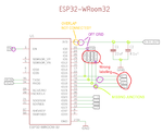
Here some issues I see, there are many more.
EA_issues.png

Klaus
 

Hi,

EAGLE offers a lot of features:
like GRID. Use 50 mil for schematics. (only rarely use other grid) --> [GRID mil 50 2 dot on]
junction, connetions, electrical rule check .....and more

It takes more time not to use it than to use it.

Here some issues I see, there are many more.
View attachment 159302

Klaus

Hi Klaus...your suggestions are very valuable.....I'll try to implement in multiple small sheets with correct labeling. Other than these issues is there any solid problem with other circuitry? Like wrong connections like stuff??
 

Status
Not open for further replies.

Part and Inventory Search

Welcome to EDABoard.com

Sponsor

Back
Top