Continue to Site

Welcome to EDAboard.com

Welcome to our site! EDAboard.com is an international Electronics Discussion Forum focused on EDA software, circuits, schematics, books, theory, papers, asic, pld, 8051, DSP, Network, RF, Analog Design, PCB, Service Manuals... and a whole lot more! To participate you need to register. Registration is free. Click here to register now.

Phase shifter circuit

Status
Not open for further replies.

jimmykk

Full Member level 3
Joined
Oct 2, 2014
Messages
158
Helped
0
Reputation
0
Reaction score
1
Trophy points
1,298
Activity points
2,863
Hi

I have a high voltage(let's say +-100Vpp) sine signal of 500khz and i want this signal to be phase shifted(+ve) by 0, 90, 180 and 270 degrees.
That is a circuit which has 500khz input signal and 4 outputs with 0, 90, 180 and 270 degrees phase shifted.
I do not want any attenuation in the circuit. I have looked into op-amp/transistor circuits with RC Components. But have not come very far with that yet.
Is integrator circuit the way of doing it? Suggestions?
 

Integrator will have a phase shift of only one value.
An input of +/- 100v @500khz , which opamp ?
 
Last edited:

Yes.... single integrator will have 90 degree phase shift but i was wondering if it is practical to use them in series to have several phase shifts.

When it comes to opamp selection, i am open for suggestions at the moment. As mentioned, i do not want any gain/attenuation(same amplitude output if possible).
 

Hi,

A CE amplifier (or equivalent) with a gain of 1 should be a 180 degrees phase shifter and a CC amplifier (or equivalent), if there is need at all, will give you a 0 degree phase shift.

I believe you are left with the 90 degrees and 270 degrees phase-shifters.
 

Hi,

A CE amplifier (or equivalent) with a gain of 1 should be a 180 degrees phase shifter and a CC amplifier (or equivalent), if there is need at all, will give you a 0 degree phase shift.

I believe you are left with the 90 degrees and 270 degrees phase-shifters.

Yes, i guess 90 degrees is also achievable if i use potentiometer with a CE amplifier output. But i am looking for a complete circuit which will output all the phases.
 

...
But i am looking for a complete circuit which will output all the phases.

Please consider taking it one at a time. I believe you could still have three or four independent circuits working together, one for each output.
 
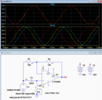
Below is the LTspice simulation of an all-pass filter which can generate phase-shifts from 180 to 360 degrees depending upon the setting of pot U2.
C1 and U2 can be interchanged to get from 0 to 180 degrees.
It uses a high voltage op amp for a 100Vpp signal.

Capture.PNG
 
Last edited:
Thanks for reply.....in the wave plot can you pls describe about the various V(out) waves with different colors. And period looks to be 2ms\0.5khz. Will this work at 500khz?
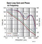
Also in the datasheet of ltc6090, there is phase change with frequency. So for our 500kkhz frequency this 70-75 degree has anytthing to say.
PHASE.JPG
Also saw that slew rate of this op amp is not the best match for our high voltage application.
 

There are so called "state-variable" 2nd-oder Filter topologies (e.g. KHN or Tow-Thomas) which are able to provide - at the same time - three outputs: Bandpass. Lowpass, Highpass. At a single frequency (the pole frequency), you can have different phase shifts (0, 90, 180, 270 (-90) deg). You will need 4 opamps including one simple inverter circuit.
 
  • Like
Reactions: d123

    d123

    Points: 2
    Helpful Answer Positive Rating
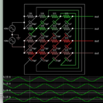
This phase-sequence network is in the circuit library of Falstad's simulator.

Constructed from resistors and capacitors. Four outputs at 90 degrees phase difference. Identical amplitude.

phase sequence network (Falstad simulator circuit menu).png

Sine sources 5V amplitude each. Total 10V.

Component values need to be adjusted for your source voltage and frequency.
 

3 simple LC delay filters will give you the required phase shifts - freq must be fixed tho'

feeding the 500kHz into transformer will give you the 3 outputs to play with, and delay ...

Or 4 x amplifiers, each fed with successively delayed signal ...
 

Hi,

I'd just generate the 90° shifted signal.
Then use two inverting stages to generate 180° and 270° signals.

Benefit:
the inverting stages usually don't need calibration,
so you just need to calibrate the 90° stage for phase shift and amplitude.

But in detail it depends on your specifications and requirements.

Problems I see:
Accuracy and precision mainly depend on
* input waveform...in case the sine is distorted somehow..
* capacitor values and drifts (usually are worse than resistor errors)

If I had to do this task, I'd try a digital signal generation.

Klaus
 

Sine sources 5V amplitude each. Total 10V.

Component values need to be adjusted for your source voltage and frequency.
This circuit looks good and straightforward. Is there any simulator where i can change the value of these R and C according to my voltage(almost >50V amplitude) and frequency(50khz).
Also one thing more to mention here is that i do not have 2 signal sources available as shown in the solution
 
Last edited:

This circuit looks good and straightforward. Is there any simulator where i can change the value of these R and C according to my voltage(almost >50V amplitude) and frequency(50khz).

Falstad's circuits are stored in a format similar to a netlist. If you don't wish to change so many components, then editing is easy in a text processing program.
Capacitors are defined on lines starting with c.
Resistors on a line starting with r.
Component value is in scientific notation.
Edit component values directly or use search and replace.
Save the file. Open it in Falstad.
Free to download and use:

falstad.com/circuit

To see the schematic in post #10:
Move mouse to Circuits menu > >Other Passive Circuits> >Phase Sequence Network.

Save it by Exporting it.

Edit the file. Save it.

Open by Importing it.

Also one thing more to mention here is that i do not have 2 signal sources available as shown in the solution

There ought to be a workaround for this. The outputs are referenced to 0V ground. This is at the centerpoint of the AC supply. Somehow the simulator only produces equal outputs if the source is twin AC supplies. (Or else if it's one source then it causes unequal outputs.) So I installed a ground icon at the join between the supplies.
 

I'm not sure 'phase-sequence network' is a good solution because the network size and accuracy of the components is decided to give optimal bandwidth. Here the frequency is fixed so such a complex arrangement isn't necessary.

I think my solution would be to drive two transformers, each having a center tapped secondary. The taps would be the output 'ground' and the winding ends would give outputs inverted with respect to each other (0, 180). Then by adding an LC delay between the primaries, the second transformer phase could be shifted 90 degrees giving the 90, 270 shifts. The only drawback would be the slight shift introduced by the transformers themselves but the OP doesn't specify whether the outputs must be exactly in phase with the inputs. Any circuit would introduce some shift anyway.

Brian.
Something like this you mean(sorry for bad drawing):
PS.JPG

- - - Updated - - -


In the all pass filter design Post#7, how would one translate the effect of potentiometer in terms of phase shift. I am looking into opamp which are much faster than LTC6090 and would like some inputs for component selections when input frequency is fixed and amplitude is high.
 

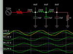
Here's a sample of the LC ladder method. Each stage introduces 90 degrees delay (approximately). It appears to need some amount of input resistance and load resistance.

phase delays inductors series caps to gnd 712 Hz 100V sine.png

Values must be adjusted to suit incoming frequency.

L:C ratio makes a difference as to how much current you want to deliver, and the available current to drive the network.

Large L, small C, small Amperes.

Small L, large c, large Amperes.
 

Something like this you mean(sorry for bad drawing):
Not quite, but nearly!
Both secondaries are center tapped and linked together with one side of the input, this is your 'ground' reference.
One transformer primary is directly driven, the other is driven from the same source but with the LC phase shift applied.
The idea is that the open ends of the secondaries are 180 degrees apart and because of the LC network in the primary of the second transformer, all its signals are shifted an additional 90 degrees.

Brian.
 

Do you really want to process 100 Vpp signal with operational amplifiers? There are very few high voltage OPs on the market (e.g. from APEX company), they are quite expensive and don't necessarily achieve 500 kHz power bandwidth.

In the all pass filter design Post#7, how would one translate the effect of potentiometer in terms of phase shift.
The transfer function of this circuit can be easily calculated and also found in many literature sources, e.g. here https://en.m.wikipedia.org/wiki/All-pass_filter

90 degree phase shift is achieved for ω = 1/RC. Advantage of this circuit is that you can tune the phase shift without affecting the magnitude, different e.g. from passive LC phase shift network.
 

Status
Not open for further replies.

Similar threads

Part and Inventory Search

Welcome to EDABoard.com

Sponsor

Back
Top