Continue to Site

Welcome to EDAboard.com

Welcome to our site! EDAboard.com is an international Electronics Discussion Forum focused on EDA software, circuits, schematics, books, theory, papers, asic, pld, 8051, DSP, Network, RF, Analog Design, PCB, Service Manuals... and a whole lot more! To participate you need to register. Registration is free. Click here to register now.

Phase shifter circuit

Status
Not open for further replies.
Do you really want to process 100 Vpp signal with operational amplifiers? There are very few high voltage OPs on the market (e.g. from APEX company), they are quite expensive and don't necessarily achieve 500 kHz power bandwidth.

Yes, the amplitude has to be high but i can be bit flexible with that if we could find a suitable op amp that can do the job properly at somewhat lower amplitudes. But the frequency has to be fixed(500khz), it cannot be changed.
Yes i ordered couple of PA78DK op amp from them. Let's see how they turn out to be. I am bit worried about GBP of them, but as i said the amplitude does not need to be amplified(same in same out). It is worth a shot.
If there is any other suitable candidate, i am open for suggestions.
 

Ideally, a GBW product of 500kHz would do.
Gain = 1, Bandwidth = 500kHz;
Gain*Bandwidth = GBW product = 1*500kHz = 500kHz.
 

Referring to all pass filter circuit, will it be huge current flowing through passive components.
What should be the ideal ratings for the passive components....would 0.1/0.25W resistors and bit high voltage rated(100/200V) capacitors a good choice for this circuit.
 

Hi,

Ideally, a GBW product of 500kHz would do.
then you have no regulation, because feedback has no influence.

Klaus
 

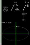
A capacitor integrator is mentioned in post #1. Capacitors and inductors automatically create 90 degree phase difference, as to voltage across it versus current through it.

By playing with component values this simulation has almost 90 degrees difference.

capacitor intergrator makes 89 deg phase delay.png

The lissajous figure is nearly circular confirming nearly 90 degrees phase delay.

The cost is severe attenuation of original signal. However the output can be used to bias a transistor which is connected to 100V supply rail.

The above single stage is sufficient to create two of your signals. Because a second transistor inverts phase.
 

Hi,

To obtain a 90-degree phase shift, use an RC filter taking the output across the resistor (i.e high-pass configuration). Design the filter corner frequency to be like two decades below your intended signal frequency (i.e. 5kHz). That way the 500kHz signal will be passed with a phase shift of 90 degrees.

Obtain a 270-degree phase shift by using a CE amplifier (or equivalent) with the gain of 1. Note that you might need to condition the filter output to cater for impedances.

My calculation gives these pairs: 470nF and 68R; 47nF and 680R; 4.7nF and 6.8k.
 
Last edited:

Hi,

If the cutoff frequency is set to 1/100 then the output amplitude will be be 1/100, too (almost).

Why not use a simple Opamp integrator?
Combined with a high quality capacitor you will get
* almost perfect 90° phase shift,
* the desired amplitude
* low output impedance
* low distortion of waveform

...I assume with the passive RC you need an Opamp anyway...but with increased part count..

Klaus
 

RC in the high pass mode will not cause this attenuation. At a corner frequency significantly lower than the signal frequency, it will allow the signal to pass without attenuation.
 

Hi,
RC in the high pass mode will not cause this attenuation. At a corner frequency significantly lower than the signal frequency, it will allow the signal to pass without attenuation.
But then it will not cause any useful phase shift. Or am I wrong?

Klaus
 

I ran this simulation and i am getting 45 Degree Phase shift but i was expecting 90 at 500khz :
sim.JPG
 

Hi,

may I ask why you expecting 90°?
with 33pF, 9k65 and 500kHz I´m expecting 45°.


****
Your circuit now uses 3 resistors, 1 capacitor nd an OPAMP.

A true integrator useses 2 resistors less, while giving almost perfect 90°... it seems you making live more difficult than necessary


Klaus
 

Hi,

may I ask why you expecting 90°?
with 33pF, 9k65 and 500kHz I´m expecting 45°.


****
Because all-pass filter gives 90 degree phase shift at cut-off frequency. https://en.wikipedia.org/wiki/All-pass_filter

I am guessing you are talking about an integrator circuit which has 2 resistors and a capacitor and op amp. where one resistor is in parallel with the capacitor.
 

Hi,

but you didn´t build an allpass. Review your circuit against the wikipedia circuit.

You built a 1st order high pass filter with cutoff frequency at 500kHz .. with an inverting gain stage.

Btw: What is RL2 used for? I´d call it useless.

Klaus
 

Yes my bad(wrong routing).
RL2 is for testing purposes only. Could have avoided that.
 

Hi,

But then it will not cause any useful phase shift. Or am I wrong?

Klaus

No, you're not wrong. It was an oversight. The phase shift is across the capacitor which is very much attenuated. The unattenuated signal which is across the resistor has no phase shift.
 

Status
Not open for further replies.

Similar threads

Part and Inventory Search

Welcome to EDABoard.com

Sponsor

Back
Top