Continue to Site

Welcome to EDAboard.com

Welcome to our site! EDAboard.com is an international Electronics Discussion Forum focused on EDA software, circuits, schematics, books, theory, papers, asic, pld, 8051, DSP, Network, RF, Analog Design, PCB, Service Manuals... and a whole lot more! To participate you need to register. Registration is free. Click here to register now.

Resonant vs. non-resonant antennas

Status
Not open for further replies.
I have evaluated box size and other parameters for a few years now and compared result with well calibrated multi-reverberation/anechoic chambers, literally world around, with aid of helpful RF-labs.
Result is most accurate when size of box is limited relative wave-length but more important is that box is regular in size and that its walls are clean and non RF absorbing.

It is easy to check if a box is usable by measuring a simple dipole for a wide freq-range. Say antenna for 2.4GHz can be measured 500 MHz-4 GHz or what range box is intended to be used for.
The biggest problem is if a box creates a standing wave distance between two walls which causes a frequency specific dip in measured antenna impedance.
This is checked by software and a popup message is telling about it if a such problem is identified but it can also for a simple antenna structure be identified as irregular frequency behavior that not belongs to antenna.
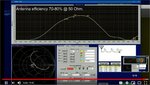
As can be seen in my video is the box used noting but reflecting walls but they are not causing any big problems as long as software can identify and correct for them.

As with other measurement methods are there a lot to say and know. A good start is to measure simple dipole antennas with well known performance or previous measured by two or three antenna method.
I create my own simple dipole antennas using CU-tape. Quartewave sleeves to block reflections along measurement cable (not ferrit!). A such antenna can easily be designed to have an efficiency above 95-98% at center-freq and have a very wide frequency range where it behaves without any impedance surprises.
Efficiency drops outside of center freq. but it does in in a very predictable way without any hick-ups which makes it easy to check if a box seems usable.

As it often is, is previous RF measurement skills and experience are important factors to do reliable and repeatable measurements and that is so also for this method.

Repeated efficiency measurement result is for me typical within in 0.2 dB with this method. That is a precision seldom reached in a anechoic chamber or multi reverberation chamber.
To reach that precision must details be taken in account such as that added cable length in chamber also must be added in free space measurement part.

Additional info about this method can be read at https://www.antune.net/wheeler and there are also links to other papers.
 
Excellent, many thanks for all the additional details!
It's easy to miss details like the (lossy) ferrite, so your detailed appnote is very useful!
 

I am doing a simple demo, tuning of an antenna and then measure its real radiating efficiency here: https://www.youtube.com/watch?v=RyMFun_KhAc

At minute 9:19 the movie you posted shows the efficiency of the Mitsubishi AM11DP-ST01-868 antenna at 2.45GHz, which is about 72%.
Do you have the same measurement done at 868MHz using the original matching network?
 

Attachments

  • 2.4G.jpg
    2.4G.jpg
    159.3 KB · Views: 86

Sorry but this earpiece was a development project many years ago and it have been reconfigured several times and I did no real initial measurement.
Anyhow is it relative easy to retune it to 865 MHz using just two components and it was a fair question, I wonder too what it could been from beginning. Everything below 1 GHz and it is seldom any need to adjust values due to stray effects and such so it is easy done in AnTune to find a suiting matching network.
If it had been a real job had I probably used three components mainly because it is easier to make it wider and more stable from impedance view but for efficiency does it not make any big difference.

Schema proposed by AnTune and implemented using Murata LQW15 inductors:
schema.png
Measured efficiency:
graph2.png
Smith Chart:
smith.png

At 865 MHz is it much the PCB ground plane length that limits antenna efficiency as its length is around 40 mm but as it is a more narrow frequency range that I need to tune for can Q be relative high so it is not bad result.
Worth mention is that above measurement is measured with earpiece placed in my hand just as in video to get correct lossy/resistive antenna load due to the hand.
If earpiece had been measured in an anechoic chamber placed at SAM had efficiency probably been a bit lower due to that a head absorbs more signals then a hand for a half sphere at 868 MHz. At 2.4 GHz is difference between hand or head minor, they absorbs about same amount.

Sorry for the a bit wide frequency range but I was lazy and didn't want to re-calibrate VNA from another ongoing measurement and it can maybe be of interest to see how a such antenna behaves for a wide freq.range as well.
 
Last edited:

Thanks for the measurements, but now I am a bit confused.
Using a chip antenna designed for the frequency range 400MHz to 1600MHz, you get better antenna efficiency (72%) at 2.45GHz, than at 868MHz (42%). Bad for Mitsubishi marketing group, they missed 2.45GHz from the list :)
The antenna datasheet claim 50% efficiency at 868MHz (-3dB on the plot).
**broken link removed**

Just as an observation, for tuning on 868MHz you use an LC matching network (47nH and 4.7pF) instead of an LL matching network that Mitsubishi recommends for 868MHz (4.3nH + 47nH, and 8.2nH).

Anyway, using the same conditions would be nice to find the best can get antenna efficiency at 868MHz, to prove that the efficiency numbers obtained at 2.45GHz are real.
 

Yes it is rather natural for an such antenna to be more effective at higher frequencies. It can almost be said to be a must as we are comparing simple antenna lengths and ground lengths shorter then 1/4 lambda for 868 MHz while at 2.4 GHz is 40 mm PCB an acceptable ground plane length as antenna radiator.
At 868 MHz is the trick to radiate at all as all lengths are shorter then a quarter wave length. No matter which antenna variation of monopole, problem is similar. If ground is too short can antenna length be infinite but still too short to radiate well.
Both antenna and PCB length are better suited in length to act as radiators at 2.4 GHz then at 868 MHz.

Mitsubishi is using a PCB length slightly longer then a quarter wavelength and almost lossless ground. That is a common practice to avoid design problems and poor performance when demonstrating own antennas.
I am using a slightly to short ground plane at 868 MHz with a number of RF-eating components that absorbs RF current if it got a chance.

Have actually not seen it before but Mitsubishi is showing same peak efficiency as I got. Good as that not always is honest shown value among all antenna brands.
They have wider efficiency-bandwidth. That is as expected and had been possible to improve as I wrote above but my higher ground-losses will always cost something.

Difference in matching values depends on a number of factors. Most important factor is that Mitsubishi is using an almost lossless groundplane and my groundplane had a lot to improve.
At 869 MHz is it not any big problem but if looking at still pictures of my PCB in the video can it be seen a yellow shaded square. That area was later covered by CU-tape during tuning to get stable less lossy ground readings.
It is not a hidden trick as it is a common practice when tuning at higher frequencies. It is one of a number of minor details that it not was time to explain in 10 minutes. Had needed several days to describe what look after and how to avoid some problems etc.. A lifetime of experiences.
Another important impedance factor is difference in ground-plane length which affect measured antenna impedance. As a monopole antenna have its counterpart, mirrored version, in ground plane is ground size just as important as antenna size. Without ground, no monopole antenna impedance measured at all.
Mitsubishi measured due to this a different impedance and must then use corresponding components to make antenna matched for 50 Ohm at 868 MHz.
My matching values are effected by hand load and as can be seen in video is also platic lid affecting antenna impedance. Mitsubishi did not add a hand or lid.

Had you expected that we should use same matching network values?
It had been a bit remarkable if we had used same component values with so different setup even if similarities are simple to see.

Efficiency numbers at 2.45 MHz are real. Better then can be measured in most a regular anechoic chambers. Have done hundreds of comparisons. It is easy is to verify that result are real both by using references in real measurement and in theory as can be seen and read in my above linked information. No one have said else since at least 20 years but I have added some PC support to simplify needed math.
Verify efficiency measurement is simple. One method is to use a well designed dipole which is about 98-99% efficiency. Check that measurement is correct showing this. Add a resistive loss as part of the antenna. A 3 dB attenuator is simple to add. Now measure again. Add reactive losses and do the math manually to check if correct values are calculated. The hard part with math behind Wheelers Cap is not to measure at resonance, that is simple as you can see in my links. Problem is more outside of resonance, which now is solved.
Efficiency at 2.45 GHz can not be related to 868 MHz by any kind of simple rule but many simulation software can do decent predictions if feed by details such as antenna and ground shape, what components exist at PCB and surrounding circuit, including speaker and battery which often are problematic RF-eating components as they are in RF-hot areas, which it often is at distance longest away from antenna feeding point due to edge effects, where battery and speaker often are found and are often resistive lossy at RF frequencies..
 
Last edited:
"It is rather natural for an such antenna to be more effective at higher frequencies." !!??
So is any frequency limit where the efficiency of "such antenna" is reaching a maximum? Is the sky limit, or is just your guess? Give me numbers please.

Tell this story to Mitsubishi, that you managed to increase the efficiency and the frequency range of their antenna (almost double above the datasheet limits) for free, and they will make you rich.

In the video, cannot see well the ground plane used by the device, but if you take a look to the antenna datasheet you will see a very nice and solid ground plane that Mitsubishi recommend for this antenna.

Most of the chip antennas that I used require an LL matching network (sometime even LLL) mainly due to small dimensions of the antennas, but is now always the case. The recommended Mitsubishi LL matching network doesn't surprise me.

I appreciate your work, but no offense, in situations like this when I see these high efficiency numbers for antennas that barely you can name antennas, I say again: is a miracle.
The problem is that myself I don't believe in miracles, especially if it happens in the RF domain..
 

Dear @vfone, with all due respect: you seem to have VERY little experience with using and designing this type of antenna.

What E Kafeman describes on this antenna makes perfect sense, as it is basically a wire printed around a dielectric core. A short radiator, not more and not less, which must be complemented by a ground plance and tuned to frequency. Radiation efficiency can be better at 2.45 GHz because radiator and ground then have a reasonable size relative to the wavelength.

that I used require an LL matching network (sometime even LLL) mainly due to small dimensions of the antennas, but is now always the case. The recommended Mitsubishi LL matching network doesn't surprise me.

There's multiple implementations for the matching network of such short antennas, and LL is one one of them. But not the only one. There are multiple ways to move around in Smith Chart. The downside of inductors is loss/Q factor and you can easily ruin efficiency if you insist that LL matching is the only solution ....
 
Last edited:

>? Is the sky limit, or is just your guess? Give me numbers please.


Antenna as short dipole/monopole is pretty linear as long as total length is assumed to be less then lambda 1/2.
Numbers, no, but needed formulas so that you can do the calculation by yourself can be found by following by me provided links.
It is else a well known antenna for any RF engineer as a short dipole often is described already at 1:st or 2:nd chapter in most antenna books as principles are relative simple.

>Tell this story
No do not tell Mitsubishi that. You can be very ensured that they already know what role length for a short antenna is as factor for antenna efficiency.

Efficiecy, how it is calculated is explained if you follow my links. Was it any problem with that?
Basically is Efficiency = Rrad/(Rrad+Rloss) but guess you not followed link that explained that part. Formula is omitting reactive factor jX, but it does not affect resistive efficiency value so it is seldom neither included in theoretical paper.

Assume a short dipole and somewhat simplified math, understandable by anyone that tries to understand at least somewhat:
Rloss is mostly Ohmic losses in transmission lines and antenna surface resistivity and does not change much with doubled frequency. Some losses are fixed and some losses are linear with skin effect.
Rrad is a bit different , it can be expressed as (20 • pi² • (antenna length/wavelength)² ) = Rrad
As can be seen is Rrad a square factor of antenna length relative wave-length and as such also then is a dominating factor for resulting antenna efficiency.

A simple example just to show how frequency may affect efficiency for a short dipole/monopole:
Say 800 MHz and a dipole of effective length of 25 mm (measured for actual antenna with FFT).
Wavelength is 370 mm.
Rrad is then calculated to 1 Ohm by using above formula.
Rloss is measured to 1.5 Ohm at my VNA.

Efficiency is then 40%. using above formula.

Same antenna but now measured at 2400 MHz.
Rrad is by using above formula calculated to 8.7 Ohm
Rloss is now measured to 2 Ohm. It is low values so VNA calibration must be well performed to be able to read with precision.
Efficiency is then = 8.7/(8,7+2) or 81%

Is it this increase in efficiency that is beyond your understandable level, a miracle-level?
You have maybe no VNA or knows how to use it so that you can confirm values and because of that thinks it must be a miracle?

It is a bit simplified calculation, just to be easy to understand for anyone and limit calculations to assumed short dipoles (less then lamda/2 but bigger then lambda/50) and as my PCB contains by frequency unlinear and RF absorbing components do I not reach 81%, just 70%.

Please understand, I am not showing any miracle. I must accept these losses as we not are living in an ideal world.
However do I often afterwards check with CU tape and similar if a particular components is causing losses that can somehow be avoided.

>Most of the chip antennas that I used require an LL matching network (sometime even LLL)

Simple world you is living in. If a typical 2.4 GHz situation, first inductor is to compensate from lacking of electrical length if ceramic antenna is too short (not always so) and as next step is often a cap to ground needed at 2.4 GHz. If 3:rd or even 4:th components is a cap or inductor depends much of size of groundplane and if matching for TIS/TRP or 50/100 Ohm/balanced, need of BIAS decoupling.
Reason for cap to ground as 2:nd component is that it often (not always) reduces harmonics at antenna, which add suppression needed to pass FCC. In many cases can it be more advantageous to place that cap as 1:st tuning component but I have not found any general rules, it depends much how stable ground is.

A parallel cap can often do same job as an serial inductor and opposite, in a complex network. If possible is often a cap to prefer as it often have less ESR and a higher SRF then an inductor.

Now is it up to you to read provided links so that I not need to feed you with each little detail and simple formulas.
 
Last edited:

Well, well, well...always I said that contradictions on the Internet is like Blowing in the Wind...as Dylan song...

Unfortunately dear volker@muehlhaus, seems that you have very little KNOWLEDGE about these antenna types. Experience is good to provide to a consulted client, but if you do for many years the same mistake (due to a lack of knowledge), mistake remain.

Is no problem to show to a client 80% antenna efficiency, for a chip ceramic antenna that have 50% efficiency (and was designed to have 50%). You can do this by using (adjusted) theory, or by playing (in your way) with the test setup components.
But this is not innovation. Is cheating. Even if by mistake you provide to a client wrong performances of a product that you sell, the name is also cheating.

End of story.
 

vfone why are you so aggressive ? Can you explain your point of view with equations ?
 

for a chip ceramic antenna that have 50% efficiency

Radiation efficiency is not that simple. The loss is not just in the antenna (meaning radiating elements), the matching network losses are very relevant. And if for the same chip antenna (aka short wire) the radiation resistance goes up because we operate it at a higher frequency, and we design a new matching network that operates into a less extreme impedance, the loss in the matching network also decreases. No miracles, just physics.

Also note that you series L is a double edged sword: it might introduce significant series R into a path that is low impedance anyway. Be careful with that. Other matching strategies might have lower loss, resulting in better efficiency.

But anyway, believe whatever you like.
 
Last edited:

Most of us, even if we not know theory behind do we have experience that a dipole antenna shorter then lambda/2 is less efficient. The shorter, the less efficient.
That is true for all short dipoles and is so well known that I doubt someone can be serious saying that this is a confused kind of cheating.

A dipole 60 mm long will have almost no efficiency used as a 10 MHz shortwave antenna where lambda/2 is 15 meter.
Same antenna may have excellent efficiency at 2.4 GHz as antenna length now is lamda/2.
Somewhere in between do we have 800 MHz, how can that be confusing in a grade that assumtion must be that surounding world is cheating?

A single wire, even if wired around a ceramic core have no dedicated efficiency, that is just silliness.
A single wire is not an antenna, it is as best only a half antenna as groundplane is the other element in a dipole.
Assuming an efficiency for just groundplane is at same level of thinking.

Two of hundreds of links that all says same thing about short dipoles:
Warren L. Stutzman och Gary A. Thiele, heavier antenna names are hard to find among now living (except Vfone then).
In their book "Antenna Theory and Design" is a short dipole described as very frequency depending in its resulting efficiency:
Always a source of easy to understand information: https://www.antenna-theory.com/basics/efficiency.php

Above links are not false, lacks knowledge and contains no "adjusted theory" and is not stating some kind of cheating as Vfone assumes.
Others are lacking an unknown kind of KNOWLEDGE which Vfone suppose he have.
This is a kind of statements that often characterizes flat-earthers and crystal healers using unknown forces to create miracles of a kind not known by deadly people.

I thought Vfone was honestly interested in my VNA measurements at 868 MHz why add did completing measurements. It is from technical view nothing new, since long accepted knowledge.
The new part is that my software is able to read directly from a VNA and sort needed data to make process of measuring efficiency very simple compare to previous methods.

Software is solving several else a bit complicated problems.
As an example, Wheelers Cap method says that antenna resistance should be measured at antenna resonance as it then is no reactive losses that interferes. It should be measured with and without a cap. Cap size should be very nearfield covering antenna, less then lambda/2 distance from antenna if possible.
Almost all antennas do however drop heavily in resonance frequency when covered by a small cap and either reading result at VNA at same frequency with/without cap or try to combine result from two frequencies will not result in correct reading.
The more narrow antenna, the bigger will resulting error become. However by using time-domain can this be solved as antenna not is moving around along cable with or without cap.
It is nothing new that this is possible math, but it is nothing that is done with aid of a mini-calculator. A PC software that is doing all heavy calculations is then very practical but for different reasons have nobody but all else known pieces together until now.
Software is since several years evaluated and compared with other measurement methods and is confirmed to be well working and very precise.
It is the first software that included matching losses (15 years ago) in optimizing calculation and the only software that can calculate optimized network of any topology in real time with data read from VNA.
It is the first software that adds auto port forwarding to VNA functions. It was added 7 years ago. It is else a function that is coming at more expensive VNA's today. With AnTune and a 20 years old HP8710 will get it as well.
It was the first software that at all provided a live VNA interface. What live is is depending on VNA and PC but PC screen refresh at least 10-20 times/sec is possible.
Live part is for many hard to understand importance of but when tuning matching networks or antenna shapes can it be compared with tuning coils in an old radio, tuning by turning a coil core and get result 1 second later is 1 second too late.
It is a bit similar situation when old analog voltmeters are preferred instead of a digital multi-meter when doing this kind of jobs.

Tuning network software is relative simple if tuning just for one frequency. This software first version was developed to make it possible to do wide band optimized networks.
It had not been a real need until I had to design the first embedded cellphone antenna and its matching network, Ericsson A238SC, Ericsson's first embedded antenna. As it was a two-band antenna where both bands needed to be matched must antenna impedance and network impedance completing each other. It can be hard to see at Smith chart in a VNA which antenna impedance that is a ideal to fit with an so far unbuilt matching network with unknown topology so a computer that instantly compared all possible variation was then a must to achieve good result, and still is.
I was back then employed at Intenna.

Software have since improved a lot but also is today's cell phone antennas demanding in new ways and needs much more then two relative narrow cellphone bands, GSM900/1800 or GSM850/1900.
Adding antenna isolation as a tuneable parameter is one new option that I hope AnTune will handle in maybe a year, but it also depend a lot on its users, what functions they find most important to add.
 
Last edited:

Radiation efficiency is not that simple.

At least we have some thoughts in common...but most of the posts above (not mine), are in contradiction with this theory, and try to introduce "miracles" into the equation.

the matching network losses are very relevant

I would reformulate this statement as: the matching network losses are relevant (without very), when the losses of the chip antenna (aka short wire) itself are VERY relevant.

series L is a double edged sword

Yes, it is like this, but (for chip antennas) most of the time is not, and have to deal with this compromise. This statement is based on many experimental facts. Check app notes from Murata, Mitsubishi, Vishay, TI, or any other chip antenna manufacturer, and you will find that most of the time the series L is their first choice. But of course not always, because this is the beauty of RF.
And when you go to check the app notes and datasheets from these chip antenna manufacturers, see what all of them have in common: Antenna Efficiency is in the range 45% to 55%.

But anyway, believe whatever you like.

There are no doubts about this, always I believe whatever I like.
 

and you will find that most of the time the series L is their first choice.

I'm actually doing full custom designs based on EM solvers (with full modelling of dielectric losses and conductor losses) and actual component S2P data that include the component losses. Then you can pinpoint where exactly what the individual contribution to total losses is and what that does to radiation efficiency.

Once you have done the EM for the antenna itselt, Optennilab which I mentioned above is great for adding the matching network, as it includes the detailed matching network losses (from component S2P data) in total efficiency optimization. And then you find that LL-matching not always the smartest choice for total efficiency.

I would reformulate this statement as: the matching network losses are relevant (without very), when the losses of the chip antenna (aka short wire) itself are VERY relevant.

You indicate that the radiator (ohmic) loss is what limits radiation efficiency, and from many careful investigations I can't agree with that.

A comment on your 50% from appnotes: What I see in my designs is that distance of the (short) radiator to ground has very strong impact on bandwidth and radiation efficiency, so I optimize that within given PCB outline. If the ceramic chip antennas for an even smaller PCB by even less distance to ground, yes that means more extreme impedance and decreases radiation efficiency.
 
Last edited:

Status
Not open for further replies.

Part and Inventory Search

Welcome to EDABoard.com

Sponsor

Back
Top