Continue to Site

Welcome to EDAboard.com

Welcome to our site! EDAboard.com is an international Electronics Discussion Forum focused on EDA software, circuits, schematics, books, theory, papers, asic, pld, 8051, DSP, Network, RF, Analog Design, PCB, Service Manuals... and a whole lot more! To participate you need to register. Registration is free. Click here to register now.

Proportional valve control using a Raspberry

Status
Not open for further replies.

Rikr09

Member level 3
Joined
Feb 14, 2013
Messages
59
Helped
0
Reputation
0
Reaction score
0
Trophy points
1,286
Activity points
1,745
Hello!

I have a pair of these valve:s https://kellypneumatics.com/download_files/MidPVspec.pdf. We tried to control them using a PWM signal from a Raspberry Pi but this is not working causing some vibrations and notable fluctuations on the output. So i decided to write you to help us with a configuration to control them.

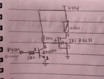
Attached the image of the circuit that im using for now:
WhatsApp Image 2020-04-23 at 12.25.23 AM.jpeg

Thanks for your attention.
 

Unsuitable high gate pull-up resistor. Try 1kohm.

What's the PWM frequency? Do you have an idea of suitable PWM frequency for this valve?
 

Hi,

you need some overvoltage protection for your MOSFET, because you are driving an inductive laod.
Zener, MOV, ..
Even a freewheeling diode may work. But mind the slow decaying current.

To simplify the circuit I recommend to use a logic level MOSFET.

If you want to drive multiple valves, then consider to use a ready to buy low side switch (driver) IC.

Klaus
 

Unsuitable high gate pull-up resistor. Try 1kohm.

What's the PWM frequency? Do you have an idea of suitable PWM frequency for this valve?

Ok, thanks for your reply, i will test with 1k.

According with the PWM frequency i did it till 2Khz and the behavior geot better but still the vibrations. The datasheet does not recommend any PWM. :???:

- - - Updated - - -

Hi,

you need some overvoltage protection for your MOSFET, because you are driving an inductive laod.
Zener, MOV, ..
Even a freewheeling diode may work. But mind the slow decaying current.

To simplify the circuit I recommend to use a logic level MOSFET.

If you want to drive multiple valves, then consider to use a ready to buy low side switch (driver) IC.

Klaus

Hello Thanks for your answer.

With this circuit we onlye wan to control one valve, is to say, one configuration for each valve. On the other side, why to use a Logi Level Mosfet? cand you recommend me one?
 

The circuit given is not for proportional control
for a conventional PWM method.
 

Hi,

why to use a Logi Level Mosfet?
As already said: to simplify the circuit. You can drive it from the Raspberry without a bjt.

cand you recommend me one?
There are so many, and many will suit your application. Just go to any electronic parts distributor or Mosfet manufacturer and use their interactive selection guides.
Then you have all at once: V, I, price, availability, package, R_DS_ON... it´s much faster when you do this on your own.

Klaus
 

Replace the input NPN with a PNP transistor
with appropriate biasing.
 

Freewheeling diode is in fact required for PWM operation, I didn't notice it's missing.

PWM frequency has to chosen so that you get almost continuous current with a certain ripple to overcome valve hysteresis. Several 100 Hz up to some kHz are typical values, depending on the valve mechanical time constant. Missing freewheeling diode will however cause abrupt current decay and thus higher vibration.
 

Hi,

I agree with FvM.
A valve is an inductive device, it's movement is controlled by magnetic field, which is proportional to current (not voltage).
Thus - with the freewheeling diode - and a suitable PWM frequency you can control the valve with PWM duty cycle.
I've done this already with hydraulic proportional valves.

I don't understand the PNP approach.

Klaus
 

Hi,
try to use uln2003 instead of 2n2222, from 100k to 1k-0.5W and STP55nf06
 

Status
Not open for further replies.

Part and Inventory Search

Welcome to EDABoard.com

Sponsor

Back
Top